<?xml version="1.0" encoding="utf-8"?><feed xmlns="http://www.w3.org/2005/Atom" ><generator uri="https://jekyllrb.com/" version="3.10.0">Jekyll</generator><link href="https://visschers.nu/feed.xml" rel="self" type="application/atom+xml" /><link href="https://visschers.nu/" rel="alternate" type="text/html" /><updated>2026-06-15T11:47:55+00:00</updated><id>https://visschers.nu/feed.xml</id><title type="html">Berik Visschers</title><subtitle>A log of repairs and creations</subtitle><entry><title type="html">Music unscrewed</title><link href="https://visschers.nu/repairs/2025/05/16/pianobox-pro.html" rel="alternate" type="text/html" title="Music unscrewed" /><published>2025-05-16T12:00:00+00:00</published><updated>2025-05-16T12:00:00+00:00</updated><id>https://visschers.nu/repairs/2025/05/16/pianobox-pro</id><content type="html" xml:base="https://visschers.nu/repairs/2025/05/16/pianobox-pro.html"><![CDATA[<h2 id="repair-for-a-friend">Repair for a friend</h2>

<p>After lifting the back cover we’re greeted with a screw stuck between the PCB and the casing.
<img src="/assets/img/repairs/pianobox_pro/8DDCC9EE-ECC5-4963-9B22-1A5D454FE1EE_1_102_o.webp" /></p>

<p>It turns out that Both screws of the computer board came loose, and the board finally unmounted itself.
<img src="/assets/img/repairs/pianobox_pro/75D7964F-3B1E-4F88-9156-E956148C5593_1_105_c.webp" /></p>

<p>This repair is simple: Remove the main PCB, refit the computer board to it. Then add some thread lock in the screw holes and tie the screws before the glue sets.</p>

<p><img src="/assets/img/repairs/pianobox_pro/E4EC6639-BDDF-4A7A-BE0C-E54011D03832_1_105_c.webp" /></p>

<p>Once assembled, the Pianobox Pro is ready for its next gig!</p>]]></content><author><name>Berik</name></author><category term="Repairs" /><summary type="html"><![CDATA[Repair for a friend]]></summary></entry><entry><title type="html">Friendly repair for a friend</title><link href="https://visschers.nu/repairs/2025/05/15/technics-radio-amplifier.html" rel="alternate" type="text/html" title="Friendly repair for a friend" /><published>2025-05-15T16:00:00+00:00</published><updated>2025-05-15T16:00:00+00:00</updated><id>https://visschers.nu/repairs/2025/05/15/technics-radio-amplifier</id><content type="html" xml:base="https://visschers.nu/repairs/2025/05/15/technics-radio-amplifier.html"><![CDATA[<h2 id="repair-for-a-friend">Repair for a friend</h2>

<p>These are the innards of the Technics Model No. SA-104.<br />
<img src="/assets/img/repairs/technics_radio_amplifier/2DB0383D-1502-40CD-B555-903EBC1DBCB9_1_105_c.webp" /></p>

<p>The radio dial wire is guided throughout the machine — quite spectacular. In the front here is the tuning variable capacitor. In the back, you see the flywheel connected to the button shaft, giving the tuning dial that extra quality feel.<br />
<img src="/assets/img/repairs/technics_radio_amplifier/DFD9DA9D-7453-4606-B6AF-20B0C747A599_1_105_c.webp" /></p>

<p>When we started, the amplifier didn’t do anything. My friend had previously replaced some transistors that are part of the power supply section, as well as a power resistor that had burned out. This was some time ago, and the repair had stopped there.</p>

<p>Now we have a look at this amplifier together and hope to get it back to operational.</p>

<p>Safety first: I trace the line voltage leads. The PCB that receives the line voltage needs to be unscrewed and put aside to gain access to the power supply section below. I wrap this PCB in a plastic bag and tape it shut. We still need to be careful with mains voltage, but the biggest risk is now one layer of plastic away.</p>

<p>We plug in the amplifier and measure the voltage coming out of the transformer. There is a -32V AC and +32V AC rail, both stable.</p>

<p>Next, I measure the DC rails after the rectifier (the black square at the lower right). These rails can be easily found — the two capacitors (big black circles at the bottom) are connected to them, one for each voltage rail. I measure these from the bottom side of the machine.</p>

<p>Luckily, the bottom plate of the machine can be removed. Vintage machines often have features that make them easier to repair, like better access.</p>

<p>I measured both capacitors — first resistance, then farads. The negative rail capacitor measured 4200µF, while it should be 4700µF. This is below its specification, but not enough for the amplifier to stop working. The other measured 4800µF — no problem.</p>

<p>I find another, much smaller capacitor that looks like it has experienced some internal pressure. Aluminum electrolytic capacitors (the ones that often look a bit like batteries) can start to boil and push up the top. Some even have grooves in the top of the housing so that overpressure is released more predictably and visibly. Measuring capacitors in-circuit doesn’t always work. In this case, I remove the capacitor to get a proper reading. It reads fine. My friend suggests replacing it, but I’d like to first find the fault before replacing anything preemptively.</p>

<p>This is the point where studying the circuit is required. Luckily, the <a href="https://www.scribd.com/document/565434651/Hfe-Technics-Sa-104-Service">full circuit diagram is documented online</a>.</p>

<p>Studying closely, we find some failed solder joints. Next time I find a broken solder joint, I’ll make some good photos to show you. But broken joints are hard to spot anyway: the solder is like a mirror, and the crack is often just a very thin black line. Now imagine such a small feature between all the lines and shiny dots of a big PCB, and you’ll understand how easy it is to miss. I found the dry solder joint by wiggling components in the power supply section of the PCB. One of the rectifier diodes felt “swampy”, sticking to whichever side you push it. Components should feel springy when pushed — that was a clear indication.</p>

<p>My friend found two 4700µF 35V replacement capacitors, and we replaced both original rectifier capacitors. I touched up the failed solder joints and double-checked some of the previous work.</p>

<p>Next, we powered up the machine, and the power supply had both negative and positive rails working.</p>

<p>However, the display lamps didn’t work, and we had no good way to test the audio.</p>

<p>First, the display lamp. We removed the lamps and found both were broken. My friend selected a blue and a white LED to replace the original 12V lamps.</p>

<p>We need a resistor to drop the 12V to something the LEDs will accept. I estimate roughly that an LED will take 2V, so we need to drop 10V at roughly 20mA.</p>

<p>The formula we need here is:<br />
<strong>U = I × R</strong> (Voltage equals current times resistance)<br />
We need to find the resistance, so we rearrange the formula:</p>

<p><strong>R = U / I = 10V / 20mA = 500 ohms</strong></p>

<p>We pick 470-ohm resistors and mount the LEDs where the glow lamps used to be. We test the preamplifier with a set of headphones and confirm that it works — both the radio and the Phono, Tape, and Aux inputs.</p>

<p><img src="/assets/img/repairs/technics_radio_amplifier/E89E83F4-D130-4B42-9959-FFCBEE020435_1_105_c.webp" /></p>]]></content><author><name>Berik</name></author><category term="Repairs" /><summary type="html"><![CDATA[Repair for a friend]]></summary></entry><entry><title type="html">Osqar shines bright</title><link href="https://visschers.nu/repairs/2025/05/07/osqar.html" rel="alternate" type="text/html" title="Osqar shines bright" /><published>2025-05-07T10:00:00+00:00</published><updated>2025-05-07T10:00:00+00:00</updated><id>https://visschers.nu/repairs/2025/05/07/osqar</id><content type="html" xml:base="https://visschers.nu/repairs/2025/05/07/osqar.html"><![CDATA[<h2 id="de-reparatiebalie">De Reparatiebalie</h2>

<p>This is Osqar,</p>

<p><img src="/assets/img/repairs/osqar/DA52A24F-6A53-4DEF-BC2B-DE32C0575D35_1_105_c.webp" /></p>

<p>Osqar can’t shine anymore.</p>

<p>His head split in two.</p>

<p><img src="/assets/img/repairs/osqar/IMG_9894.webp" /></p>

<p>And his power supply stopped working.</p>

<p><img src="/assets/img/repairs/osqar/6FD8F170-CE1B-40DC-9A7E-AB4FAB4B610B_1_105_c.webp" /></p>

<p>The output shows a mere 2.8V AC, where we would expect 12V.</p>

<p>Let’s deep dive into the design of this 12V power supply.</p>

<p><img src="/assets/img/repairs/osqar/IMG_9896.webp" /></p>

<p><img src="/assets/img/repairs/osqar/02E4AB0C-3F07-4694-82D3-39FD37605C58_1_102_a.webp" /></p>

<p>This is its circuit diagram:</p>

<p>On the left we start with the 200V AC input, which first goes through a Fusable Resistor and then enters a Full Bridge Rectifier.</p>

<p>From here we enter a region of black magic. This region lasts all the way until the transformer – the two whirlpools facing eachother near the right edge of the circuit. Lets skip this section for now and concentrate on what comes after the transformer.</p>

<p>After the transformer, the voltage level is 12V AC. This low voltage section of the circuit has a separate PCB. It includes a fuse; a switch to select either off, low or high (the component with a T above it, the T represents a button, it isn’t drawn perfectly clear here); and a resistor and switching diode to turn down the light in the low mode; lastly the lamp is on the right bottom of the circuit, represented with another whirepool like curve, facing down.</p>

<p>Interestingly, the high / low selection does not save any power in the low mode. Instead it warms up a big resistor to reduce the lamp brightness. This resistor is a 5W one, it is the white rectangular component next to the multimeter in the photo above.</p>

<p>Now for the center part of the circuit. Lets start at the transformer on the right. Transformers can be made smaller and more efficient by increasing the frequency they work at. The power company in europe delivers 50Hz, which is quite a low frequency. You’ve heard the tone before, it is part of the sound that a vacuum cleaner or kitchen applience makes, some power adapters produce a soft 50Hz hum, and near power lines you often hear the static fibrate with this low frequency. 50Hz, it turns out, requires big and inefficient transformers. To solve this inefficiency, this circuit runs the transformer at a much higher frequency. To produce the higher frequency, first the 50Hz is rectified and made into 325V DC (230V AC equals 650Vp-p, which gives 325V rectified). The center of the circuit contains two power transistors configured such that they will start oscillating, driving the transform at a predictable high frequency.</p>

<p>This type of power supply is called a switch mode power supply (SMPS). There are many variants of SPMSs, this is an early version. Modern SMPSs designs look very different. They are based on one or more power MOSFETs and a dedicated chip for driving them.</p>

<p>On to the repair. I test each component one by one and find no issues. Bummer.</p>

<p>It took me way longer to find that the transformer had failed than I want to admid. Transformers are hard to measure with a multimeter. When you measure their resistance, most will read close to zero ohms. If a transformer is shorted internally, it will also read very close to zero ohms. See the problem? I first unsoldered the transformer and then convinced myself that the transformer resistance on the 325V side was too low, being below 1ohms. The high voltage side of a transformer should read a higher resistance than the low voltage side. A value below 1ohms only makes sense for a really powerful transformer or a very low voltage transformer side. In this case its neither.</p>

<p>Replacing the transformer will be difficult. There tranformer did not come with any specification or product number.</p>

<p>Time for plan B.</p>

<p>I found a generic dimmable 12V adapter, and a 220V dimmer board.
<img src="/assets/img/repairs/osqar/1A63ED4E-CD19-4BBF-81FF-665578085835_1_105_c.webp" /></p>

<p>I fit the two devices inside the housing of the old transformer. I had to remove some plastic from the adapter housing. The fit was tight, but it worked out fine.
<img src="/assets/img/repairs/osqar/D3F3DF1D-C518-435A-A18D-0D8525323C55_1_105_c.webp" /></p>

<p>Now osqar can shine again.</p>

<p>Unfortunately I couldn’t restore the original electronics. But there are some benefits to a refresh: The 12V adapter is more efficient than the old power supply, and the dimmer makes sure that lowering the light intensity actually saves some energy. Also the dimmer setting used to have only high and low intensity and now became continuously adjustable.</p>

<p><img src="/assets/img/repairs/osqar/194E5A34-DC52-49AE-A316-97D181E88230_1_105_c.webp" /></p>]]></content><author><name>Berik</name></author><category term="Repairs" /><summary type="html"><![CDATA[De Reparatiebalie]]></summary></entry><entry><title type="html">Blown capacitor</title><link href="https://visschers.nu/repairs/2025/05/07/lenco-record-player.html" rel="alternate" type="text/html" title="Blown capacitor" /><published>2025-05-07T10:00:00+00:00</published><updated>2025-05-07T10:00:00+00:00</updated><id>https://visschers.nu/repairs/2025/05/07/lenco-record-player</id><content type="html" xml:base="https://visschers.nu/repairs/2025/05/07/lenco-record-player.html"><![CDATA[<h2 id="de-reparatiebalie">De Reparatiebalie</h2>

<p><img src="/assets/img/repairs/lenco/7E015DC0-954C-47A7-A6EA-FF97E5A79990_1_105_c.webp" /></p>
<video autoplay="" loop="" muted="">
    <source src="/assets/img/repairs/lenco/IMG_0186_na.mov" type="video/mp4" />
</video>]]></content><author><name>Berik</name></author><category term="Repairs" /><summary type="html"><![CDATA[De Reparatiebalie]]></summary></entry><entry><title type="html">Sugden A25 - Professional Repair</title><link href="https://visschers.nu/repairs/2025/05/07/sugden-amplifier.html" rel="alternate" type="text/html" title="Sugden A25 - Professional Repair" /><published>2025-05-07T10:00:00+00:00</published><updated>2025-05-07T10:00:00+00:00</updated><id>https://visschers.nu/repairs/2025/05/07/sugden-amplifier</id><content type="html" xml:base="https://visschers.nu/repairs/2025/05/07/sugden-amplifier.html"><![CDATA[<h2 id="professional-repair">Professional Repair</h2>

<p>A repairman asked me to repair his Sugden A25 amplifier. What an honour!</p>

<p>The machine works, but there is an audible 50Hz tone coming from the speakers. I immediately conclude that this must be the rectifier capacitors.</p>

<p>After receiving the machine and opening it up, there is a clear visual confirmation:
<img src="/assets/img/repairs/sugden_a25/06E4BA5D-E48B-404F-9BA7-ED197DA171A9_1_105_c.webp" /></p>

<p>Both capacitors have formed a slight bulge due to internal pressure buildup.</p>

<p>I remove both, and they measure 1000x less than their rated value. Due to the way they are laid out on the PCB, and the height of the machine, I need to order the exact size: 35mm by 20mm, 10mm lead spacing. These are Rubycon branded capacitors — Sugden did select quality components! I can only order a batch of 500 Rubycons of the correct value and size. I check in with the customer to see if they mind another brand. I get a reply of full confidence in my expertise and go ahead with the repair.</p>

<p>Let’s be diligent, now that I’ve received full confidence. I inspect each component on the PCB and see some interesting features.</p>

<p><img src="/assets/img/repairs/sugden_a25/DFCBE419-7B73-4E8A-8463-70F2D2EECCE7_1_105_c.webp" />
<img src="/assets/img/repairs/sugden_a25/A366D98F-8BA2-4872-94EC-5225AA1DD436_1_105_c.webp" /></p>

<p>Three things to notice here:</p>

<ul>
  <li>The PCB seems to have been bent along the power transistor legs</li>
  <li>The PCB shows some slight discoloration around the transistors</li>
  <li>The ceramic capacitors have developed a white, stubbly beard</li>
</ul>

<p>I first deal with the capacitors. For each type, I desolder one or two and measure their value out of circuit. Quite a few capacitors are out of spec:
<img src="/assets/img/repairs/sugden_a25/C1294DC2-A971-48AF-8D16-717EAC0BC43A_1_105_c.webp" /></p>

<p>The two big ones are the rectifier capacitors that failed completely. The others still have some value, but less than specified (whatever it says on the outside ±20%, for most capacitors). Also, ideally, if there are four capacitors with the same specified value, you wouldn’t want to see one being +20% and another being -20%.</p>

<p>I leave the capacitors that measure fine — they’ve survived over 40 years, and chances are good they’ll survive another 40. For the out-of-spec capacitors in the photo, I order replacements.</p>

<p>The PCB bend marks are not visible on the side with the traces, nothing to worry about. There is quite some 40 year old flux residue on the solder side of the PCB, which I clean up using some isapropanol alcohol.</p>

<p>There isn’t much point in testing the amplifier without having good capacitors in place. Instead, I do some work on the front panel.
<img src="/assets/img/repairs/sugden_a25/AD626992-F186-4CEB-BAAA-A35DF43F41D6_1_102_o.webp" /></p>

<p>One of the knobs is missing, and another is split in two.</p>

<p>I ask a friend with a 3D printer if they fancy printing a knob.
<img src="/assets/img/repairs/sugden_a25/A5924D2B-890C-4FAF-A1AF-22F52BDED6ED_1_105_c.webp" /></p>

<p>I measure and sketch the knob specifications, then visit my friend with this piece of paper. About an hour later, we have the first attempt printed.
<img src="/assets/img/repairs/sugden_a25/052EBB59-468A-457B-A508-5311E9CB059F_1_102_o.webp" /></p>

<p>In the photo above, the original knob is on the left, and the printed knob is on the right. I ask my friend if the inset can be printed as well. The next day, they deliver:
<img src="/assets/img/repairs/sugden_a25/C3B08F01-BC64-444D-BDFC-AAC035086574_1_105_c.webp" /></p>

<p>I spend 10 minutes per knob flattening the print lines, then sanding, then painting.
<img src="/assets/img/repairs/sugden_a25/DBDF2207-D0B3-42C6-AA77-FBDDCC127455_4_5005_c.webp" /></p>

<p>One gets a different treatment. Being printed in red, I add a few layers of red spray paint with a nice gloss.
<img src="/assets/img/repairs/sugden_a25/728F99A1-C5CC-45A7-BE14-8B9144B23DE3_1_102_o.webp" /></p>

<p>I’m proud of the result:
<img src="/assets/img/repairs/sugden_a25/43D713BD-6054-41CF-A7AA-EC3AE0B78C6C_1_105_c.webp" />
<img src="/assets/img/repairs/sugden_a25/CDF1085A-D216-44C5-BBB9-BD44AAACD2CE_1_105_c.webp" /></p>

<p>I fix the knobs in place with some silicone glue. This type of glue does not become fully hard, therefore the buttons can be replaced later if needed.</p>

<p>I show the result to the customer: “A red button?!” he responds jokingly. I tell him he’ll receive an extra black button and can decide which one to use himself.</p>

<p>Once the capacitors arrive by mail, I continue with the electrical repair. With the new capacitors in place, I test the amplifier. The 50Hz hum is gone. The volume knob crackles when turned. Otherwise, the amplifier works as expected.</p>

<p>I fix the volume knob using some contact spray. I spray a bit of contact spray through the small gaps of the potentiometer housing — on the Sugden that’s the blue box right behind the volume knob — then rotate the volume knob up and down for a minute or two.</p>

<p>Time to go the extra mile. I check the documentation for the bias current and find it should be between 80 and 100 mA. To measure the bias current, remove one of the four fuses near the power MOSFETs and replace it with a multimeter in current measurement mode.
<img src="/assets/img/repairs/sugden_a25/IMG_0426.webp" /></p>

<p>The Sugden measures around 110 mA on either channel. I tweak both trimmer pots to set the bias current to 90 mA. Then I wire the input and output of the Sugden to an oscilloscope and check how well the output matches the input when feeding a 5 kHz sine wave. The scope trace looks excellent — repair done!</p>

<p>Lastly, I apply some silicone glue to the bigger electrolytic capacitors. This amplifier won’t be shaken much, but I want to deliver quality. A bit of silicone glue relieves the stress on the capacitor leads when the amplifier is moved or shaken.</p>

<p>When the customer comes to pick up their amplifier he tells me that the amplifier has been turned on for most of its life. This explains the rectifier capacitor issue perfectly. These rectifier capacitors have been maintaining a voltage for 40 years, they’ve held up well: The replacement capacitors have something to live up to.</p>]]></content><author><name>Berik</name></author><category term="Repairs" /><summary type="html"><![CDATA[Professional Repair]]></summary></entry><entry><title type="html">Sony DD Walkman: Broken Main Gear Replacement</title><link href="https://visschers.nu/repairs/2025/03/06/sony-dd-walkman-broken-gear.html" rel="alternate" type="text/html" title="Sony DD Walkman: Broken Main Gear Replacement" /><published>2025-03-06T14:00:00+00:00</published><updated>2025-03-06T14:00:00+00:00</updated><id>https://visschers.nu/repairs/2025/03/06/sony-dd-walkman-broken-gear</id><content type="html" xml:base="https://visschers.nu/repairs/2025/03/06/sony-dd-walkman-broken-gear.html"><![CDATA[<h2 id="repair-job-take-home-assignment">Repair job take home assignment</h2>

<p>
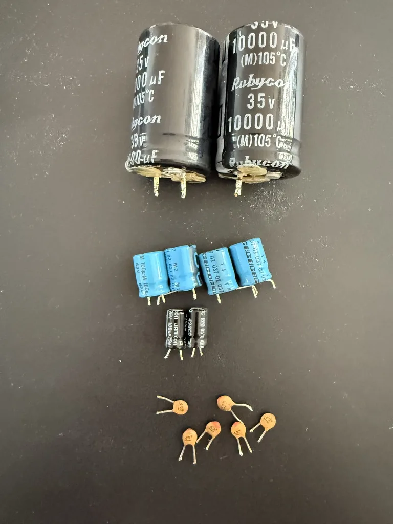
I agreed to take this repair home. This repair needs parts to be ordered. Also the repair is quite intense.
Especially if it is the first time to open a Sony DD Walkman. This device is high-tech from another era.
There are plenty of tiny screws, all different. There are springs and clips that have a tendency to fly off and vanish.</p>

<p>A repair café setting, where kids are running around, a customer is waiting, time pressure, etc, is no place
for such a repair.</p>

<h3 id="issue-description">Issue description</h3>

<p>After many years of service, this Direct Drive Walkman developed some issues:</p>

<ol>
  <li>A plastic gear, which is cast around an iron ring, tears open.
After that, the Walkman will still play cassettes, but the broken gear will cause
the audio to stop briefly every 2 seconds or so.
Also when listening to the mechanics when the Walkman is playing, a tick sound can be heard.
every 2 seconds or so.</li>
  <li>The Fast Reverse does no longer work. With no tape inserted both reel drive spindles turn in opposite
directions.</li>
  <li>The Play, Stop, Fast Forward, Fast Reverse buttons get stuck in the pressed position
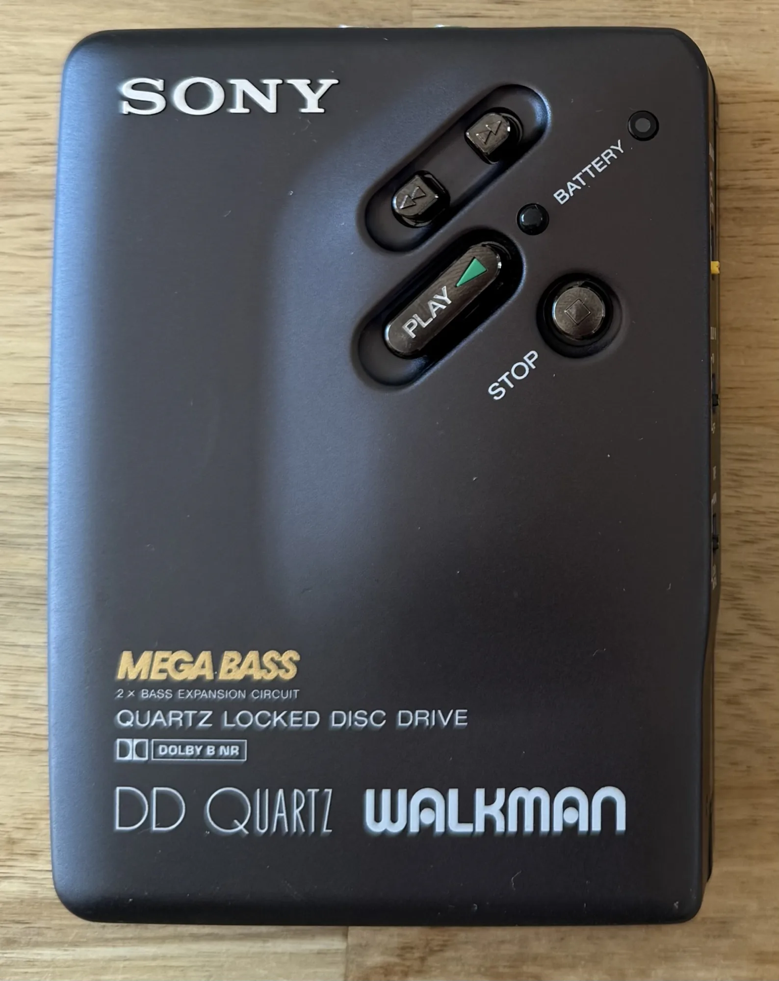
</li>
</ol>

<p>The walkman
<img src="/assets/img/repairs/sony_walkman/walkman_front.webp" /></p>

<p>The broken gear:
<img src="/assets/img/repairs/sony_walkman/walkman_broken_gear.webp" /></p>

<p>
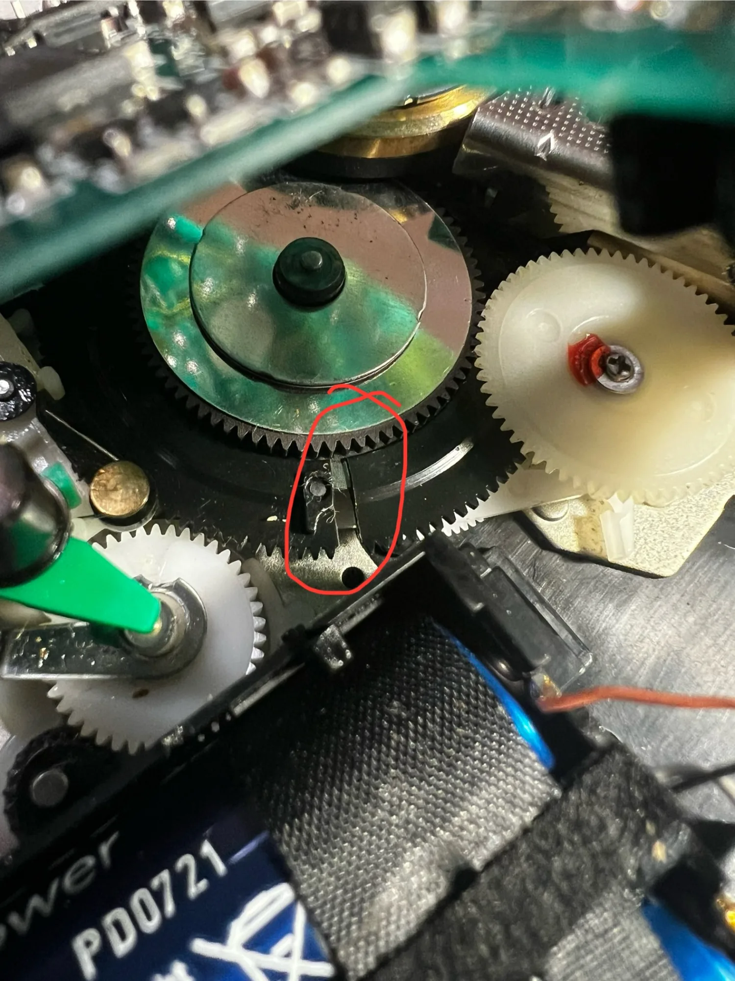
The gear likely breaks because it is tightly fit around a metal wheel. Plastic and metal have different thermal expansion coefficients,
causing the metal wheel to expand faster than the plastic. When the Walkman gets sufficiently hot, the expanded metal wheel can break the plastic gear open.</p>

<p>Fix Your Audio has a <a href="https://fixyouraudio.com/tutorials/sony-dd-series-step-by-step-repair-guide-for-dummies/">great tutorial on how to disassemble, replace the gear and lubricate the Walkman</a>,
which I used during the repair. If you want to repeat this repair, make sure to follow their instructions.</p>

<h3 id="requirements">Requirements</h3>

<p>
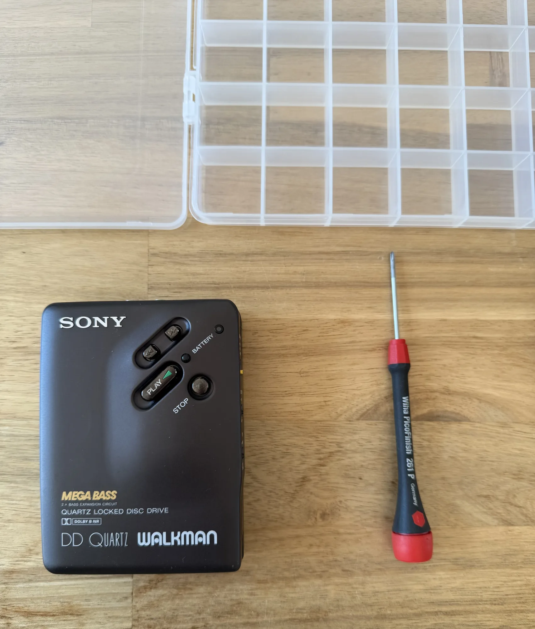
Tools and consumables used:</p>

<ul>
  <li>
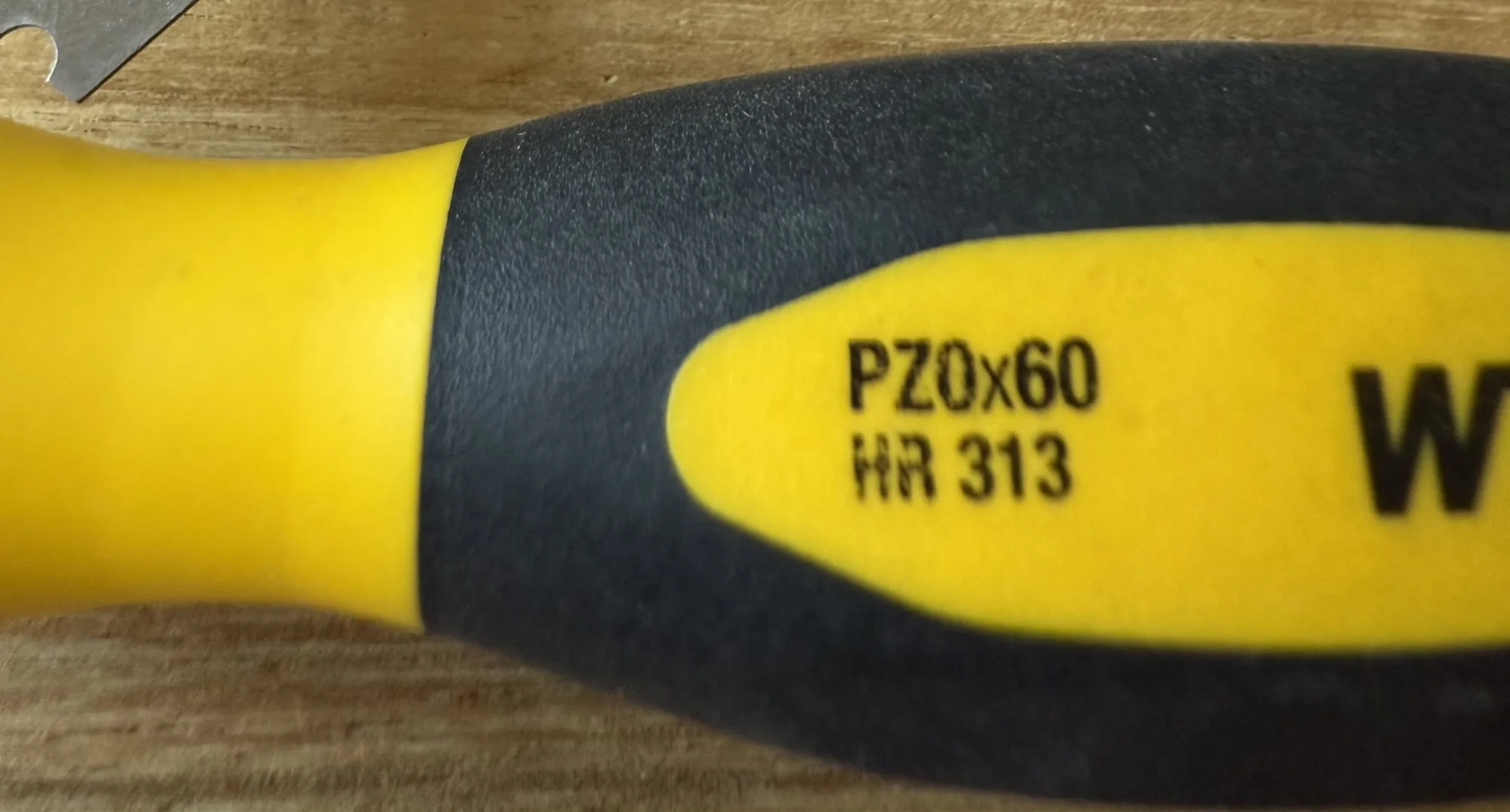
Wiha PZ0x60 HR313 screwdriver</li>
  <li>Tiny tweezers for the springs</li>
  <li>Soldering iron</li>
  <li>
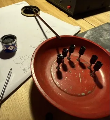
Storage box with many compartments for holding the screws and other parts</li>
  <li>Flatnose pliers, for bending metal</li>
  <li>Size 3 flat screwdriver, for bending metal</li>
  <li>Tin, Flux</li>
  <li>Q-tips</li>
  <li>Isopropyl Alcohol for cleaning</li>
  <li>Grease</li>
  <li>Light oil</li>
</ul>

<p><img src="/assets/img/repairs/sony_walkman/PZ0x60_HR313_screwdriver.webp" />
<img src="/assets/img/repairs/sony_walkman/walkman_partbox.webp" /></p>

<h3 id="disassembly">Disassembly</h3>

<p>Step one in disassembly are the screws on the outside of the case.</p>

<p>There are two screws holding the door in place, and three more holding the front.
These screws have different sizes.</p>

<p>Tip:</p>

<ul>
  <li>Make a photo before removing the screw</li>
  <li>Remove the screw, place it in a compartment of the container</li>
  <li>Make a photo of the container with the screw compartment centered</li>
</ul>

<p><img src="/assets/img/repairs/sony_walkman/walkman_partbox_in_use.webp" /></p>

<p>
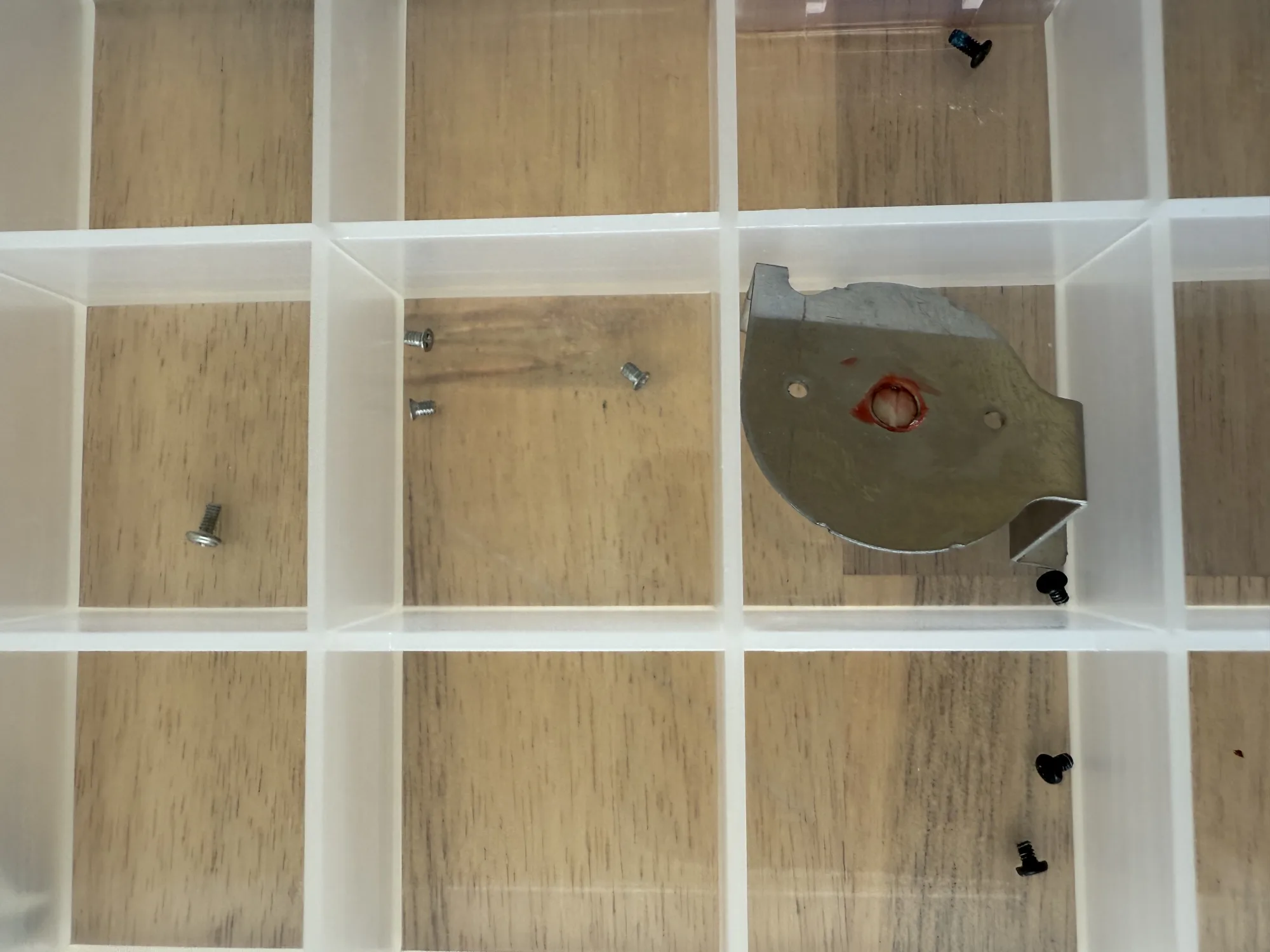
With this process, during assembly it is pretty simple to find out what part goes where.
Make sure it is clear from the <strong>photo alone</strong>, which location on the device and which compartment the screw is in.</p>

<p>
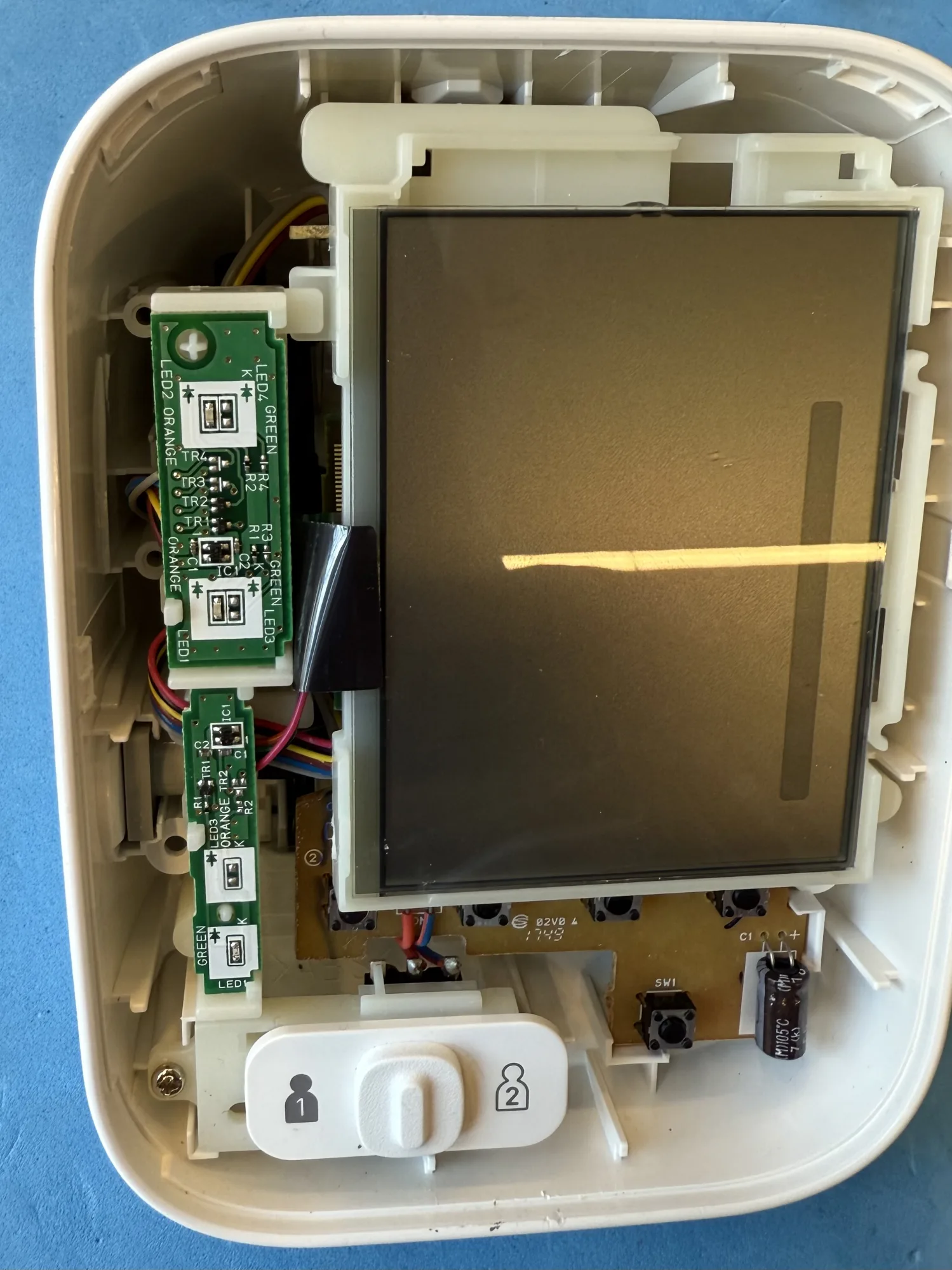
Once the door and front are off, you can undo the screws of the PCB.</p>

<p>Careful with the tiny wires, they don’t need much force to break.</p>

<p>Take enough pictures so that you know which wire goes where, in case they do break.</p>

<p>When the screws are loose, lift the PCB. The main gear will be visible. Rotate it manually and find if it is cracked, order a <a href="https://fixyouraudio.com/product/sony-tcm-d3-walkman-new-center-gear-repair-kit/">replacement main gear from Fix Your Audio</a>.
The Sony DD has the same gear as the TCM-D3 apparently. Or they are not too different.</p>

<p>
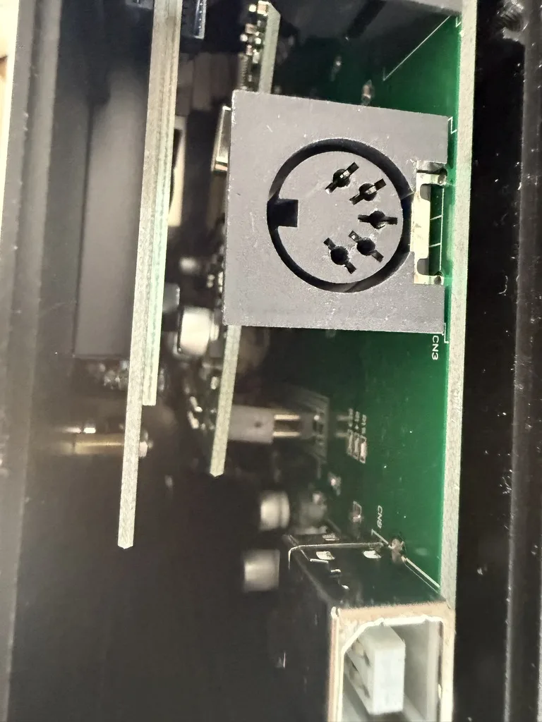
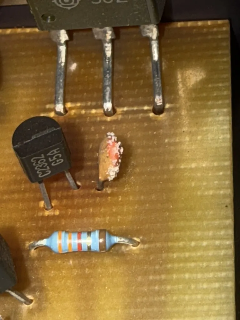
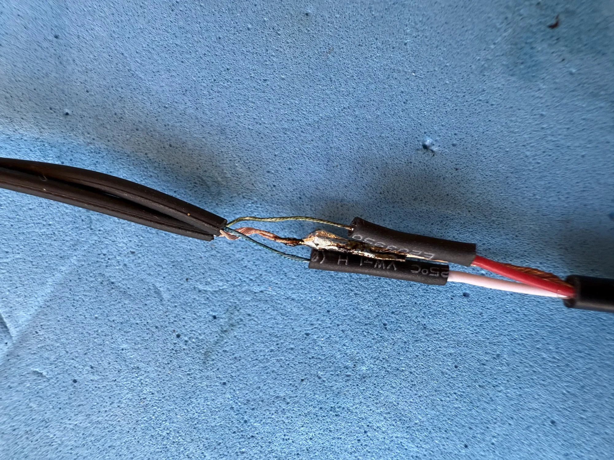
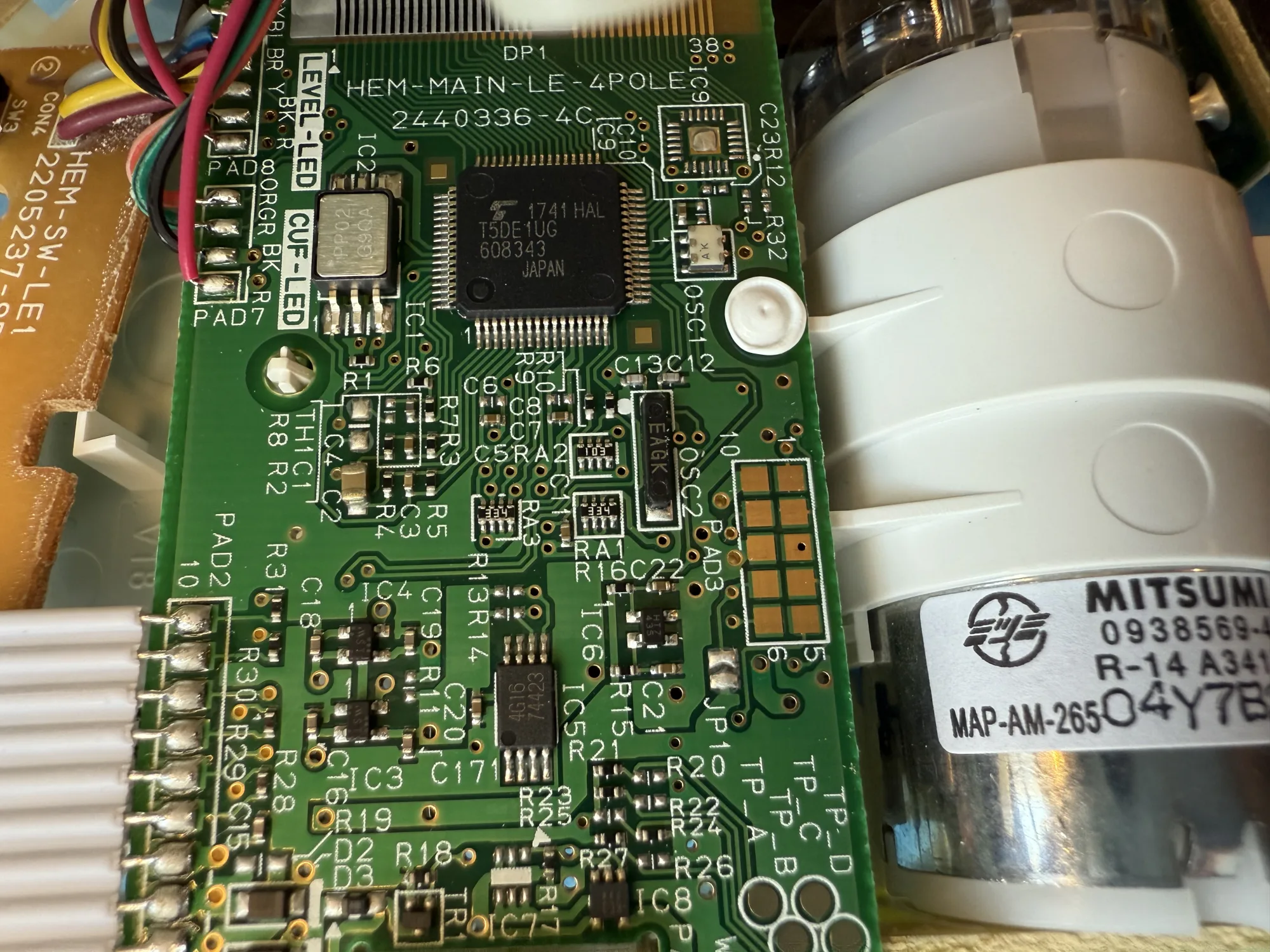
To be able to access the mechanics, you will need to desolder the tape head from the PCB.
<img src="/assets/img/repairs/sony_walkman/walkman_audio_head.webp" /></p>

<p>
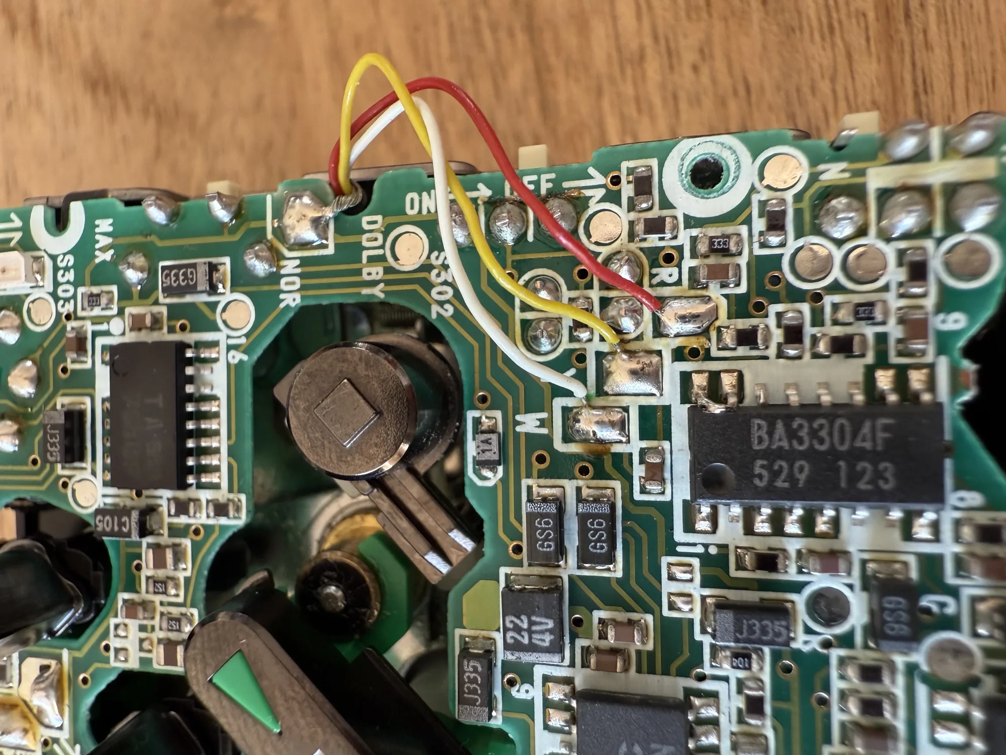
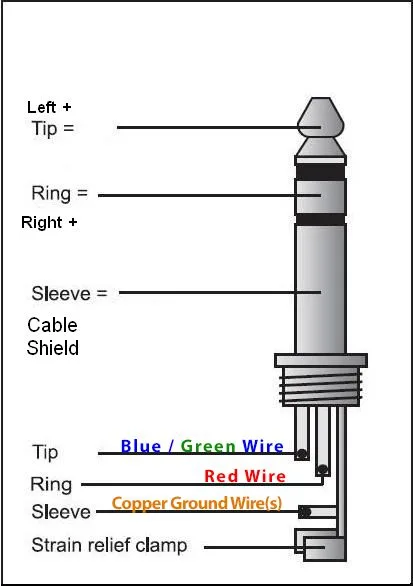
There are four wires: ground (unshielded) in the top right, white, yellow and red.
The PCB silkscreen helpfully shows single letters indicating the wire colors. (Nice attention to detail, Sony!)</p>

<p>
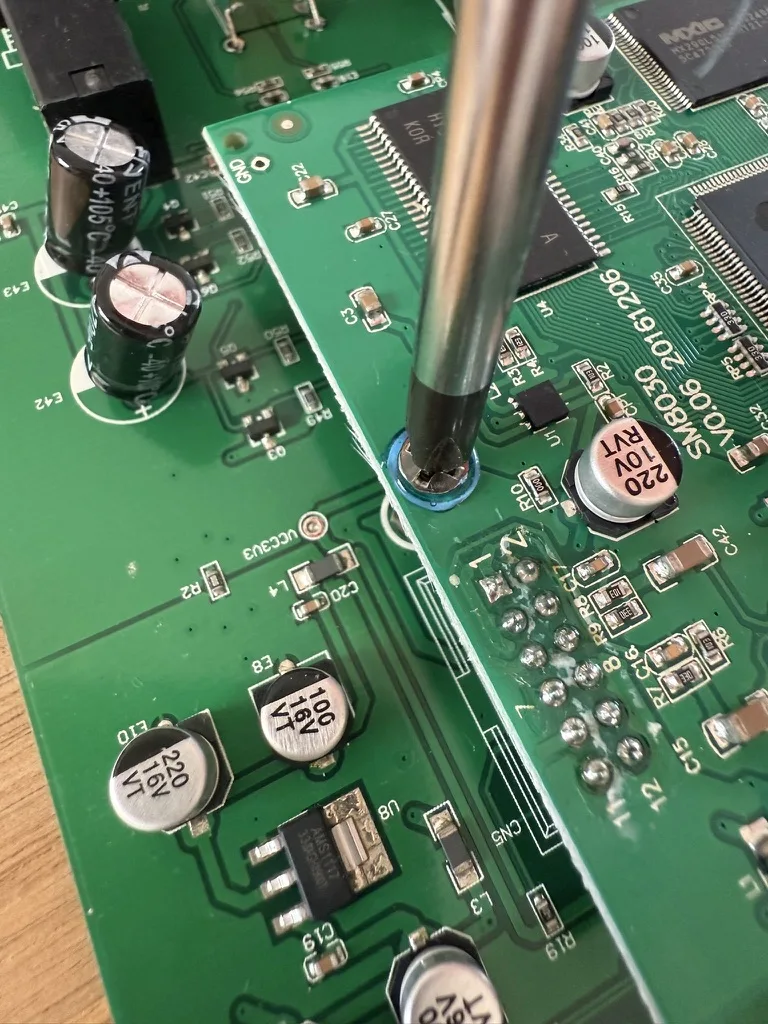
Once the wires are desoldered, stow away your soldering iron. You’ll need it again to fix these wires at the end.</p>

<p>
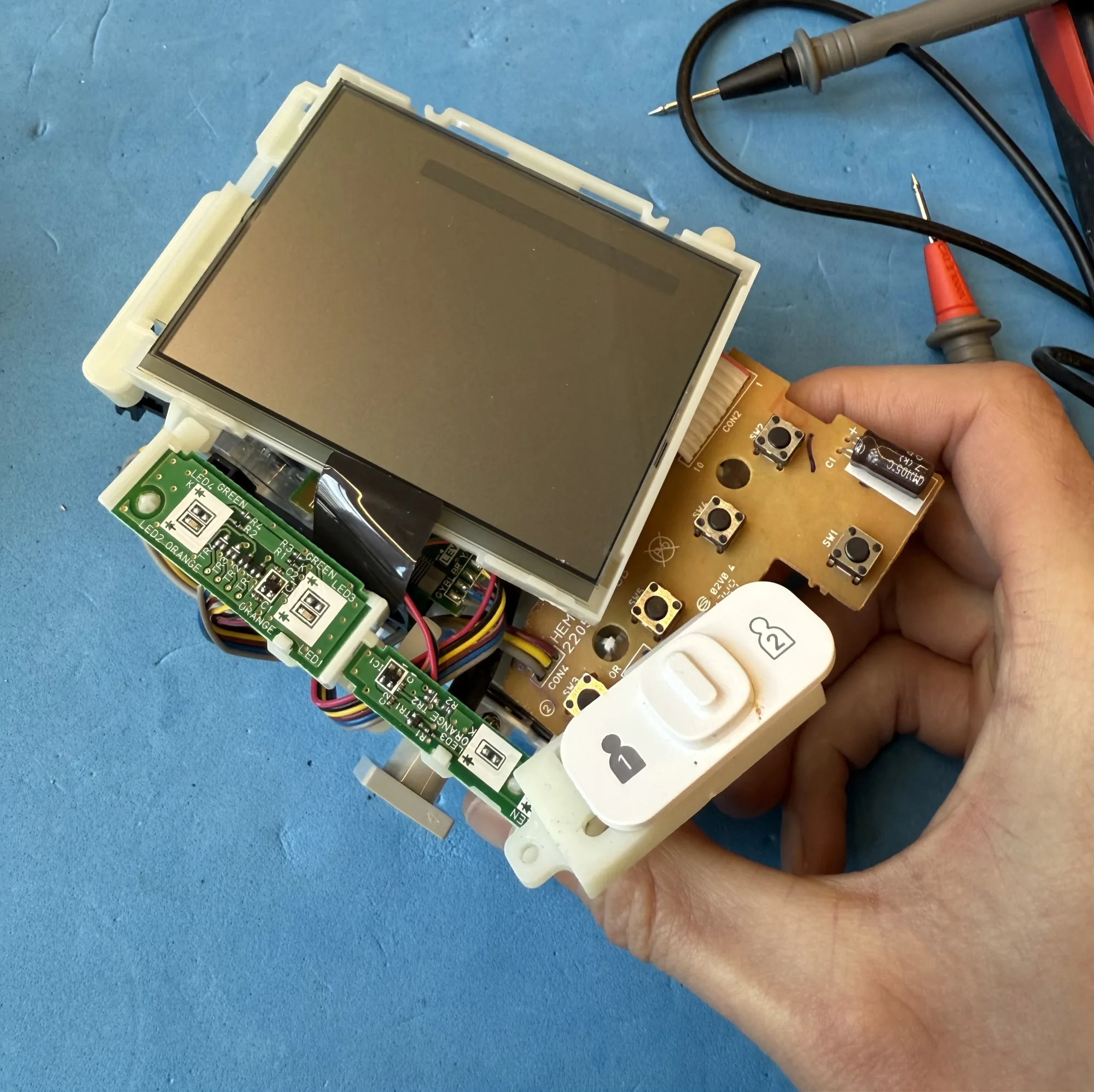
Flip the PCB over, careful not to break any of the other wires.</p>

<p>
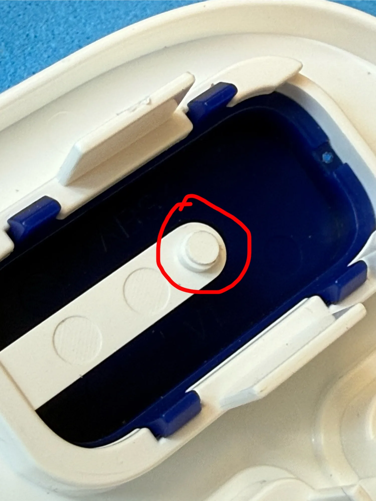
Remove the Play, Stop, Fast Forward and Fast Reverse buttons. After removing the button, also remove the lever below it.
The Stop lever is held in place with a tab. Force it out.</p>

<p>
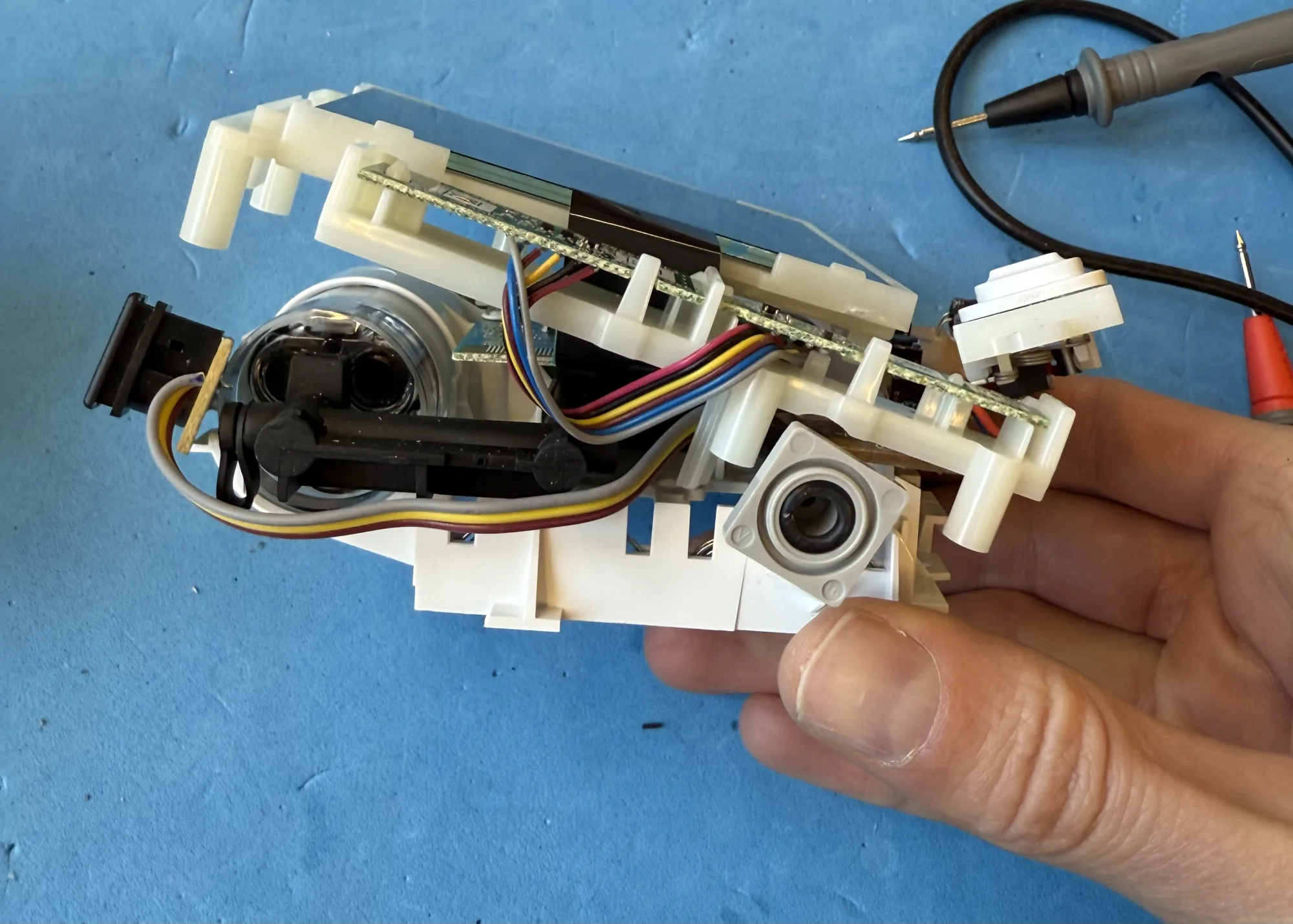
Remove the capstan wheel by removing its cover and the three screws on the tape side.</p>

<p>Remove the motor.</p>

<p>Remove the gear that is secured with a screw on top.</p>

<p>Remove the audio head lever by first removing the snap ring, then the tiny spring, then gently wiggle it out.
The lever is held in place by the plastic frame of the tape head on the tape side. Hold the tape head up
while pulling the lever out. Take your time. Gentle.
<img src="/assets/img/repairs/sony_walkman/walkman_audio_head_lever.webp" /></p>

<p>
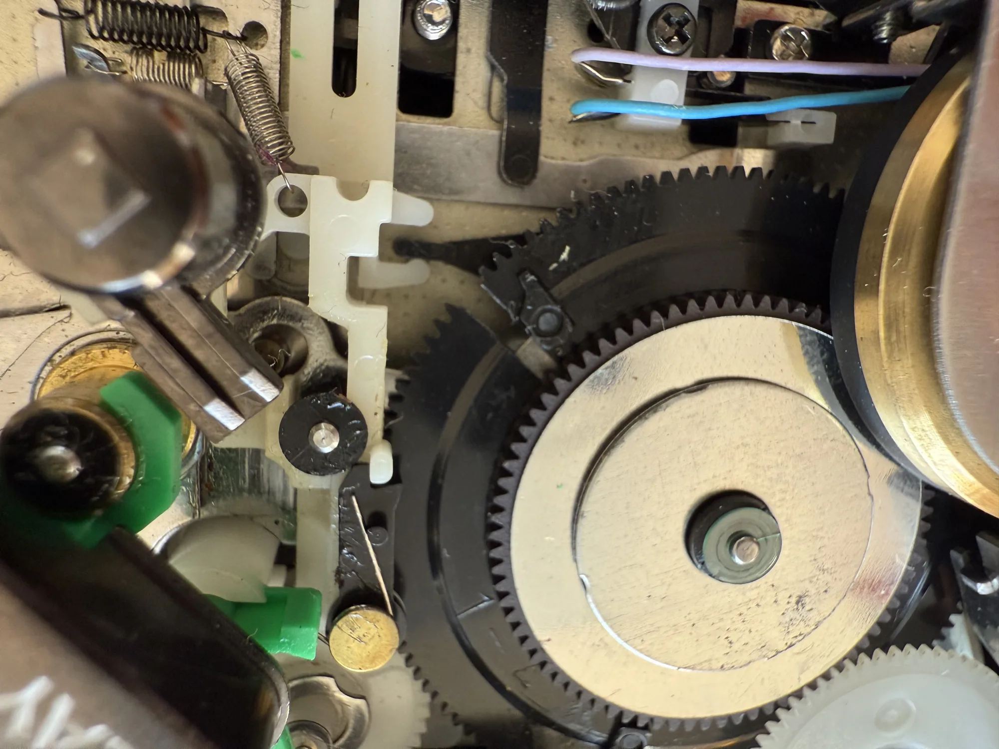
Pull the main gear assembly up. Do this gently. There is a spring below that wants to fly.
Move slowly, then the spring will relax and stay where it is.
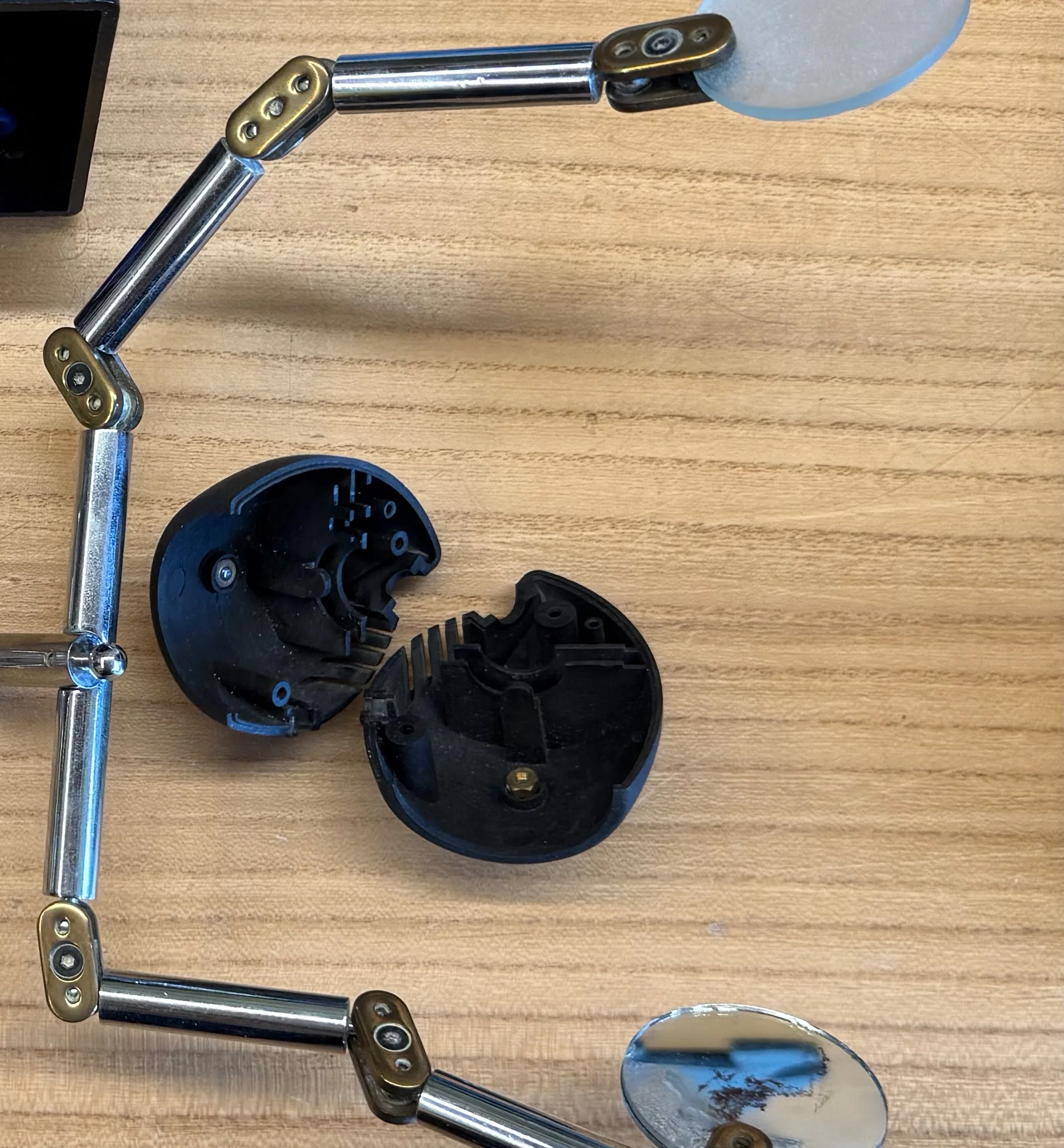
</p>

<h3 id="main-gear-repair">Main gear repair</h3>

<p>The Fix Your Audio manual shows that the main gear must be separated from its accompanying smaller gear on top.
I’ve tried, but these two gears are inseparable. Maybe the DD walkman has a slightly different main gear stackup.
<img src="/assets/img/repairs/sony_walkman/replacement_main_gear.webp" /></p>

<p>
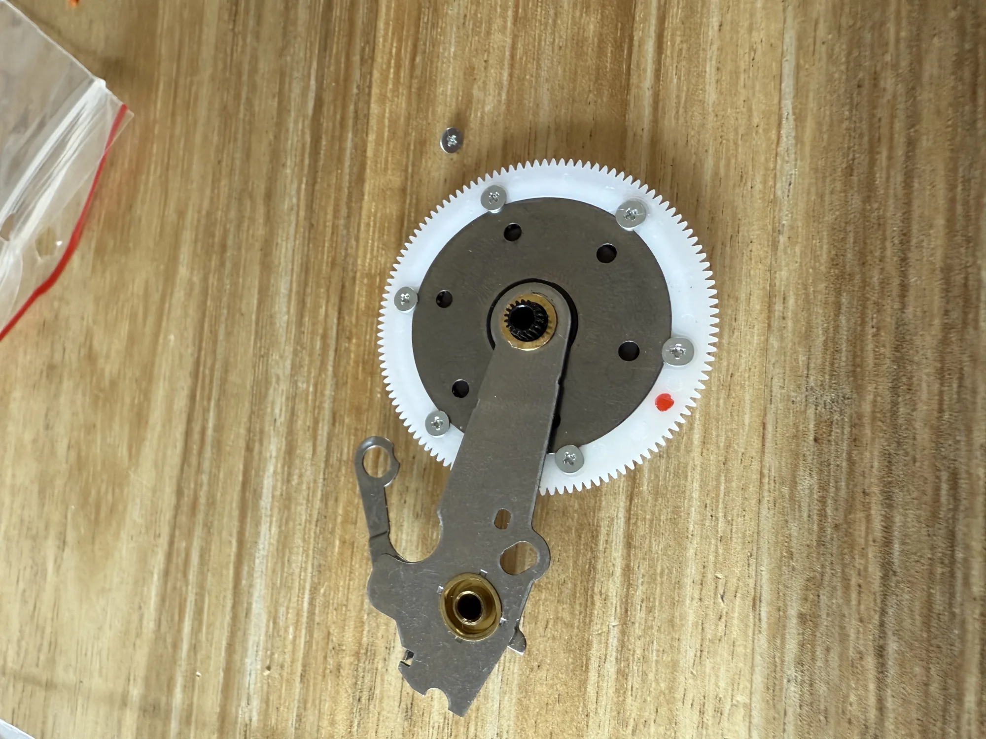
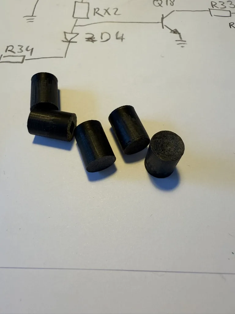
Anyway, the broken gear can easily be removed from its metal support. The replacement part is screwed on.
So there is actually no need to separate the top gear from the stack.</p>

<p>
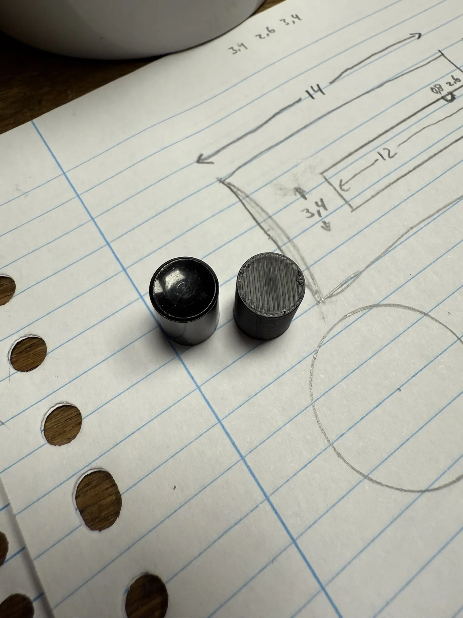
Note the red dot, indicating the bottom of the plastic gear. This makes it much easier
easy to mount the gear with the correct side up!</p>

<p>Fix Your Audio did a nice job of creating a repair part. This part is designed by someone with a Walkman passion.
Marking the components with color ink to indicate top / bottom shows how thoughtful they are of the repairmen.</p>

<h3 id="cleaning-and-lubricating">Cleaning and lubricating</h3>

<p>Clean the moving parts. The sliding bushings can be cleaned on the inside using a paper rod Q-tip:
<img src="/assets/img/repairs/sony_walkman/walkman_clean.webp" /></p>

<p>Clean the button levers and travel ways. This should free up the buttons.</p>

<p>
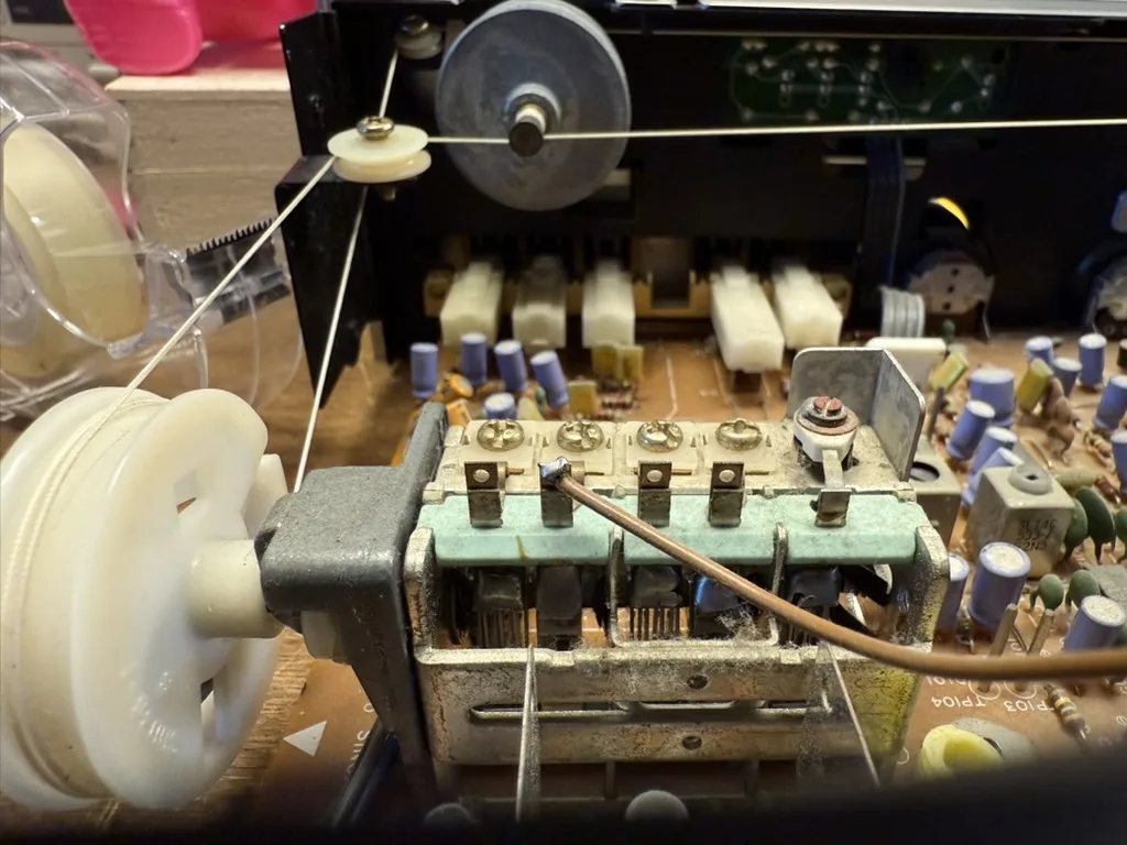
With the main gear and button action fixed, it is time to look at the Fast Reverse action.</p>

<p>First place back gears, capstan wheel, and buttons.</p>

<p>
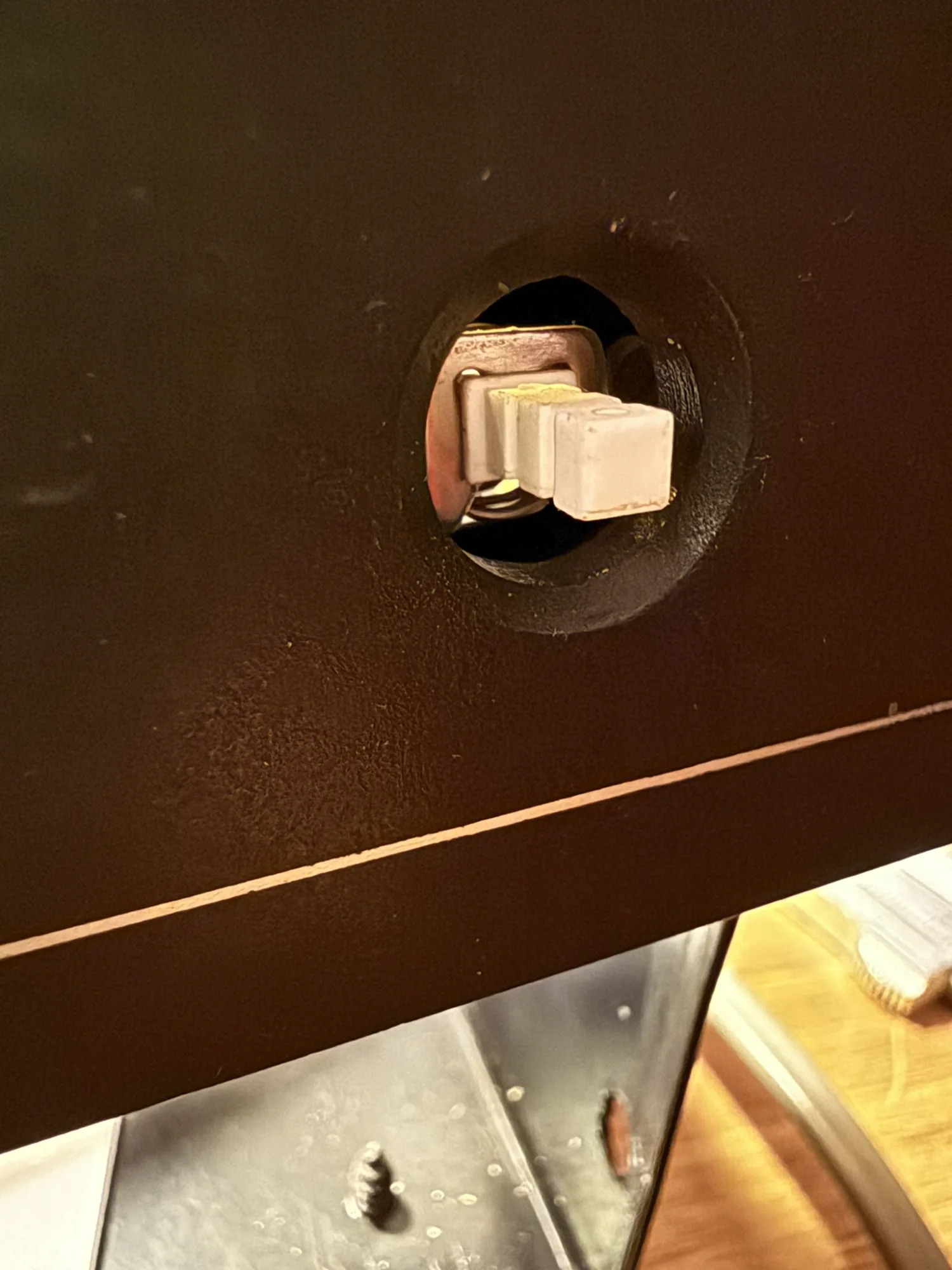
The reverse action issue happens due to a metal lever being bend. Probably a mix of stuck buttons, user pressing hard and aging makes the lever bend downwards.
When the lever is too low during Fast Reverse, it inadvertently engages the fast forward gear, causing the reel drive spindles to rotate in opposite directions.</p>

<p>
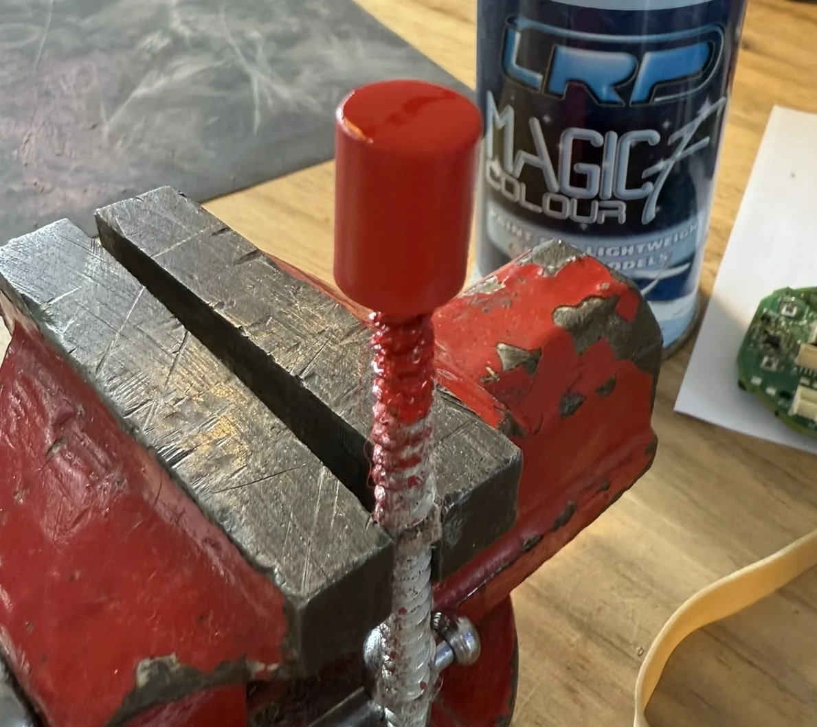
The metal sheet can be bent back up using pliers:
<img src="/assets/img/repairs/sony_walkman/walkman_fix_rew.webp" /></p>

<p>Use a screwdriver to keep the middle of the lever down, while lifting the gear side up. Bend a little, then test, then bend a bit more.
Repeat this until the reverse action works both this side up as well as tape side up. Then bend a bit more again.</p>

<p>Now, reassemble the Walkman and enjoy some music from 1995!
<img src="/assets/img/repairs/sony_walkman/walkman_music.webp" /></p>]]></content><author><name>Berik</name></author><category term="Repairs" /><summary type="html"><![CDATA[Repair job take home assignment]]></summary></entry><entry><title type="html">THE BILLIARD COMPUTER IS BACK ONLINE!</title><link href="https://visschers.nu/repairs/2025/03/01/biljartcomputer.html" rel="alternate" type="text/html" title="THE BILLIARD COMPUTER IS BACK ONLINE!" /><published>2025-03-01T12:30:00+00:00</published><updated>2025-03-01T12:30:00+00:00</updated><id>https://visschers.nu/repairs/2025/03/01/biljartcomputer</id><content type="html" xml:base="https://visschers.nu/repairs/2025/03/01/biljartcomputer.html"><![CDATA[<h2 id="repair-café-de-bieb-utrecht">Repair Café De Bieb, Utrecht</h2>

<p>The repair day is nearing its end, I had a lot of fun repairing <a href="/repairs/2025/03/01/omron-blood-pressure-monitor.html">a medical device</a>.
What more can one ask for?</p>

<p>I roam around to see what repairs are in progress on the other tables when I get called over for a micro USB replacement job.</p>

<p>The customer shows me this device:
<img src="/assets/img/repairs/biljartcomputer/biljartcomputer.webp" /></p>

<p>What. Is. That?</p>

<p>“A computer, for playing billiards”, the customer explains.</p>

<p>There is an HDMI plug sticking out of the device. This must be similar to a Chromecast, but instead of displaying YouTube commercials, it tracks and shares your billiard scores!
I guess there is a community, challenging each other for competitions. Meeting IRL, and using these devices to share their match outcomes.</p>

<p>A whole world I didn’t even know exists!</p>

<p>On to the repair. The micro USB port that powers the device has ripped off.</p>

<p>That is not uncommon for USB powered devices.</p>

<p>One of the repairmen on De Bieb specializes in USB port replacments, they’ll fix one in under 10 minutes.
This is my first USB port replacement..</p>

<p>Let’s peek inside:
<img src="/assets/img/repairs/biljartcomputer/biljartcomputer_inside.webp" /></p>

<p>Next to the ripped off conector, we see a voltage regulator, a USB-A port and another micro USB port. Underneeth the
heat conducting tape is a CPU and HDMI driver IC. On the center bottom is a micro-SD card holder. Here is where your scores will be stored off-line.</p>

<p>A WI-FI or bluetooth antenna can be seen snaking up and down, in the top right corner.</p>

<p>A detail of the place where micro USB port used to be:
<img src="/assets/img/repairs/biljartcomputer/biljartcomputer_broken_usb.webp" /></p>

<p>The pads that held the USB port in place have been pulled off. Other than that, the damage is minimal.
I tell the customer that this repair will succeed. They react a bit sceptical.</p>

<p>The five pads that look like a cross-walk (“zebra-path” in Dutch, such a great word) are “<a href="https://en.wikipedia.org/wiki/USB_3.0#PINOUTS">the USB pins</a>”
while the shiny silver looking pads on top are connected to the “USB shield”.</p>

<p>To get a sense of scale, the zebra-path width is roughly 3mm. My iron tip is 2.4mm wide.</p>

<p>The two pads that have been ripped off used to connect to the USB shield.
The fact that only these pads were ripped off tells us that the original USB port was not soldered properly.
It should have been soldered to the pads above, but it wasn’t.</p>

<p>This USB port is for powering the device, the power is delivered over the two outermost zebra-path pads.
The second-from-the-left pad is also needed, the resistor below the zebra-path tells a charger that a
power hungry device is present. The last two pads are the data lines (up and down), and are not connected
to anything on the PCB, in this case.</p>

<p>This specific micro USB connector is a bit special: The two mounting pins are a little closer together than normal.
The mounting pins fit into the oval holes in the PCB. A regular micro USB port will have them to the side of the port.
This port has them tucked underneeth, which makes soldering much much harder.</p>

<p>Luckily repair café De Bieb has these less-common parts on stock.</p>

<p>I need to take care of two things:</p>

<ul>
  <li>The new micro USB port is properly affixed to the PCB</li>
  <li>The new micro USB port has the five zebra path pads connected to its leads</li>
</ul>

<p>I could have, and maybe should have, used the hot air soldering station.</p>

<p>I didn’t. The soldering station has to be found and set up. My regular soldering iron was ready for use.
Also, there are other ports and tiny components just near to the ripped off port. Heating up the whole area risks loosing them.</p>

<p>I push on, using my regular iron. Lets do this!</p>

<h3 id="this-is-how-i-replaced-the-micro-usb-port">This is how I replaced the micro USB port</h3>

<p>I use a D24 (spade shaped) tip on my T12 iron. I find this size ideal.
It manages well on pretty big amounts of copper. And with some finesse, you can work on 0.2mm features like these.</p>

<ul>
  <li>Clear the solder from the PCB using flux, a tin sucker and wick</li>
  <li>
    <p>Solder the matching micro USB port side lugs to the PCB</p>

    <p>Carefull here. I had some solder entering the USB port. To get it out:</p>

    <ul>
      <li>Push a USB plug as far as possible into the port, pushing the tin aside, and take the plug out again.</li>
      <li>Heat the port until the solder inside melts</li>
      <li>Repeat</li>
    </ul>

    <p>After three times, the connector fully fit into the port. Extra snug.</p>

    <p>Next time I’ll use less solder.</p>
  </li>
  <li>
    <p>Solder the USB port pins</p>

    <p>Using the spade style soldering tip:</p>

    <ol>
      <li>Add flux. Add enough flux. Flux makes difficult soldering jobs doable</li>
      <li>Make sure a tiny layer of tin sticks to the tip of the iron</li>
      <li>Get the amount of tin right, use flux to keep the tin fluid</li>
      <li>
        <p>Now, with the tinned side of the tip facing downward, press the USB pins down onto the PCB pads</p>

        <p>The iron tip is much bigger than the pins and pads. No worries though, if you use flux, the tin will creap between
the metal parts and clear the places where it shouldn’t be. <strong>Do not add tin directly</strong>, add flux intsead.</p>
      </li>
      <li>Press down for 2-3 seconds until a nice sizzle starts</li>
      <li>Now pull the iron tip away from the pads and port</li>
      <li>Let the area cool a bit, then repeat until it looks decent</li>
    </ol>

    <p>I did manage to touch the voltage regulator with the soldering iron (see below).</p>
  </li>
  <li>
    <p>Lastly, Use isopropyl alcohol (IPA) with Q-tips to clean the flux from the PCB and port</p>

    <p>Some types of flux will damage the PCB traces and components over time, if it is left uncleaned</p>
  </li>
</ul>

<p>The new port soldered:
<img src="/assets/img/repairs/biljartcomputer/biljartcomputer_soldered.webp" /></p>

<p>Once the device is assembled, we walk to a presentation display and plug the biljartcomputer into the HDMI port; then plug a USB adapter in the repaired USB connector.
We see the boot screen of biljartcomputer.nl</p>

<p>THE BILLIARD COMPUTER IS BACK ONLINE!</p>

<p>We don’t have a billiard table nearby, would have been nice to see the device in action!</p>

<blockquote>
  <p><strong>Soldering advice</strong></p>

  <p>The parts that need to be soldered should be at least 250 degrees C, for at least half a second.</p>

  <p>This means you press the iron tip onto the joint. Wait until everything is hot.
Keep it at that temperature for a second or two. Then remove the tip while not moving the components.
Wait for the parts to cool down before trying again.</p>

  <p>Do not stroke components with the soldering iron. Do not try to knead the tin into place.</p>

  <p>In. Wait. Out. Wait.</p>

  <p>Trust that the tin will flow between the metal and away from clearances.</p>

  <p>In case the joint is not good, repeat from the beginning. Do not press on when things go sideways.</p>

</blockquote>]]></content><author><name>Berik</name></author><category term="Repairs" /><summary type="html"><![CDATA[Repair Café De Bieb, Utrecht]]></summary></entry><entry><title type="html">Computer Speaker Jack Replacement</title><link href="https://visschers.nu/repairs/2025/03/01/computer-speakers-jack-replacemen.html" rel="alternate" type="text/html" title="Computer Speaker Jack Replacement" /><published>2025-03-01T12:00:00+00:00</published><updated>2025-03-01T12:00:00+00:00</updated><id>https://visschers.nu/repairs/2025/03/01/computer-speakers-jack-replacemen</id><content type="html" xml:base="https://visschers.nu/repairs/2025/03/01/computer-speakers-jack-replacemen.html"><![CDATA[<h2 id="repair-café-de-bieb-utrecht">Repair Café De Bieb, Utrecht</h2>

<p>The 3mm Jack Plug of these computer speakers is mangled up pretty bad:
<img src="/assets/img/repairs/jack_replacement/speakers.webp" /></p>

<p>In the cubbord I find a decent audio cable with jack plug attached.</p>

<p>After deciding on the length, I get to soldering:
<img src="/assets/img/repairs/jack_replacement/soldering_audio_cables.webp" /></p>

<p>Soldering such tiny cables is fiddely.</p>

<p>Some cheap audio cables have aluminium cores that are impossible to solder.</p>

<p>Avoid those.</p>

<p>If you must connect aluminium cores, then do not try to solder them. Try to use crimps instead. Good luck!</p>

<p>Both audio cables I’m soldering are made of copper. One with silicon sleves, one with enamelled cores.</p>

<p>I turn up the heat to 400C, so that the soldering iron can burn off the enamel from the enameled core.
Once the enamel is removed from the tip of the wire, the heat can be turned down to 250-300C.</p>

<p>Use plenty of flux-core tin and make sure all the cores are properly tinned before continueing.</p>

<p>I measure the continuity between the cores and the jack plug.
For sterea audio jacks, from tip to the back, the order is left, right, ground.
<img src="/assets/img/repairs/jack_replacement/jack_plug.webp" /></p>

<p>Double check that the <strong>ground</strong> of the jack side is connected to <strong>ground</strong> on the speaker side.</p>

<p>On the cable with the replacement jack plug, the right channel has reddish enamel and the left channel has greenish enamel, Cute!</p>

<p>I add some shrink tube over the soldering job on the left and right cores.
The shrink tube has a tendency to shrink while the joint is being soldered.
That is no problem though, I can snip off the shrunk part and use the rest.
Or wiggle the shrunken part over the solder joint. Either way, keep in mind
to add shrink tube <strong>before</strong> soldering the joint.</p>

<p>In this case I used electrical tape as an outer insulation, which also protects the soldering joint a little from anyone jerking the cable.
Nothing is perfect, and this fix is mediocre. The customer is happy, and that is most important.</p>]]></content><author><name>Berik</name></author><category term="Repairs" /><summary type="html"><![CDATA[Repair Café De Bieb, Utrecht]]></summary></entry><entry><title type="html">Under Pressure: Breathing Life into a Medical Device</title><link href="https://visschers.nu/repairs/2025/03/01/omron-blood-pressure-monitor.html" rel="alternate" type="text/html" title="Under Pressure: Breathing Life into a Medical Device" /><published>2025-03-01T11:30:00+00:00</published><updated>2025-03-01T11:30:00+00:00</updated><id>https://visschers.nu/repairs/2025/03/01/omron-blood-pressure-monitor</id><content type="html" xml:base="https://visschers.nu/repairs/2025/03/01/omron-blood-pressure-monitor.html"><![CDATA[<h2 id="repair-café-de-bieb-utrecht">Repair Café De Bieb, Utrecht</h2>

<p><img src="/assets/img/repairs/omron_blood_pressure/omron.webp" /></p>

<p>What a treat, a <strong>medical device</strong>!</p>

<p>Another repairman asks if I can take over this repair.
The story of what is broken is not immediately clear.
I probably missed some communication. The only thing I hear from the customer is “Does not work!”.</p>

<h3 id="investigation">Investigation</h3>

<p>Well… The display clearly does something when batteries are inserted. Maybe the batteries are low?</p>

<p>Measuring the battery voltages, they look to be good. Nonetheless, I grab a lab PSU and feed the device 6V over the battery terminals.</p>

<p>Not much changes.</p>

<p>The display shows historical measurements when pressing the left and right arrow buttons.
The customer insists that the device does not work.
Pressing the Start / Stop button does not start the measurement procedure, which, apparently, it should.
I somehow get in the date and time setting mode, without knowing how I got there. Worse, I can’t seem to exit the date and time setting mode.</p>

<p>I try to learn a bit more about the device by reading the <a href="https://www.bloeddrukmeterswebshop.nl/media/handleiding/Omron-m3-2014.pdf">Omron M3 online manual</a>.
Alas, the manual does not even mention the date and time setting mode. There is also no overview of functions and how to activate them; Bummer.</p>

<p>Enough with the speculation and studying, time for some <strong>action</strong>!</p>

<h3 id="open-it-up">Open it up</h3>

<p>First remove two screws here:
<img src="/assets/img/repairs/omron_blood_pressure/omron_bottom.webp" /></p>

<p>Then remove the front panel by lifting it with a spudger, undoing the plastic tabs:
<img src="/assets/img/repairs/omron_blood_pressure/omron_inside_top.webp" /></p>

<p>Removing the inside from the casing is still a challenge. There are two steps:
<img src="/assets/img/repairs/omron_blood_pressure/omron_remove_innards.webp" /></p>

<ol>
  <li>First remove the screw just below the LED indicator PCB</li>
  <li>
    <p>Lift the two plastic tabs that fix the battery container to the outer casing.</p>

    <p>From the back, push the battery container to the front and out while lifting the tabs on the inside, so that the container can slide freely.</p>
  </li>
</ol>

<p>Then the intestines come lose:
<img src="/assets/img/repairs/omron_blood_pressure/omron_innards_front.webp" />
<img src="/assets/img/repairs/omron_blood_pressure/omron_innards_side.webp" /></p>

<p>Beauty, both simple and complex at the same time. On the inside there are 4 different PCBs!</p>

<p>Each PCB has a dedicated function:</p>

<ul>
  <li>LED indicators</li>
  <li>Buttons</li>
  <li>Motor and battery connection</li>
  <li>MCU, Motor controller, Display driver</li>
</ul>

<p><img src="/assets/img/repairs/omron_blood_pressure/omron_mcu.webp" /></p>

<p>This devices has been designed using high end 3D design software, clearly.</p>

<p>A core feature of this device is being accessible: There are big letters on the display, bright indicators and big buttons.
About half the device space is dedicated to User Interaction.</p>

<h3 id="issue-and-root-cause">Issue and root cause</h3>

<p>Once the device is open, I quickly determine the issue and its cause.</p>

<p>The Start / Stop button micro-switch does not make a clickity sound when pressed. The other switches do.
Testing with continuity mode on the multimeter, my hypothesis is proven: The Start / Stop microswitch is pushed one too many times.</p>

<p>We have a set of 6x6 mm microswitches in stock.</p>

<h3 id="the-repair">The repair</h3>

<ul>
  <li>Snip out the broken microswitch using side cutter pliers</li>
  <li>Clear the PCB holes of old solder and snipped pins using a soldering iron, a tin sucker and solder wick</li>
  <li>Select a microswitch from the 6x6 mm set that looks right</li>
  <li>Solder the new microswitch in place</li>
</ul>

<p><img src="/assets/img/repairs/omron_blood_pressure/omron_replacement_switch.webp" /></p>

<p>Testing the new switch with a multimeter, it works flawlessly.
With batteries connected, the pump can be started by pressing the new microswitch.</p>

<p>Time to reassemble.</p>

<p>Once fully assembled, the Start / Stop button does <strong>not</strong> work.</p>

<p><strong>Again.</strong></p>

<h3 id="the-repair-continuation">The repair, continuation</h3>

<p>I remove the front panel and start inspection.</p>

<p><strong>SW1</strong>, the replaced microswitch, as you can see on the above picture,
is just a bit taller than the other microswitches.</p>

<p>(…dare I say “it is a less-microswitch”?)</p>

<p>When the front panel is mounted, the Start / Stop button permanently presses the microswitch.</p>

<p>One could redo the whole operation and mount a better fitting microswitch there. But let’s not waste time.</p>

<p><img src="/assets/img/repairs/omron_blood_pressure/omron_button_trim.webp" />
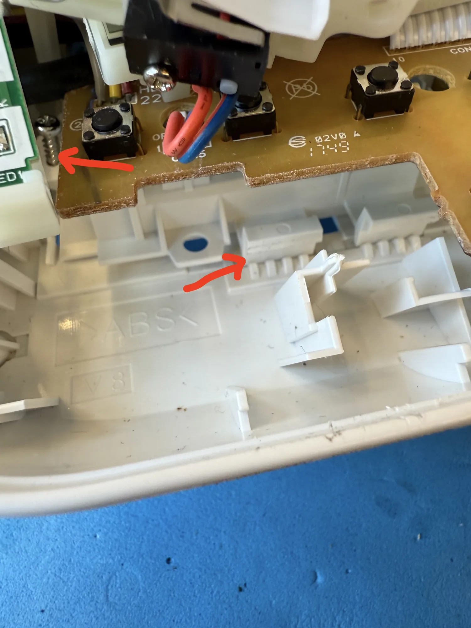
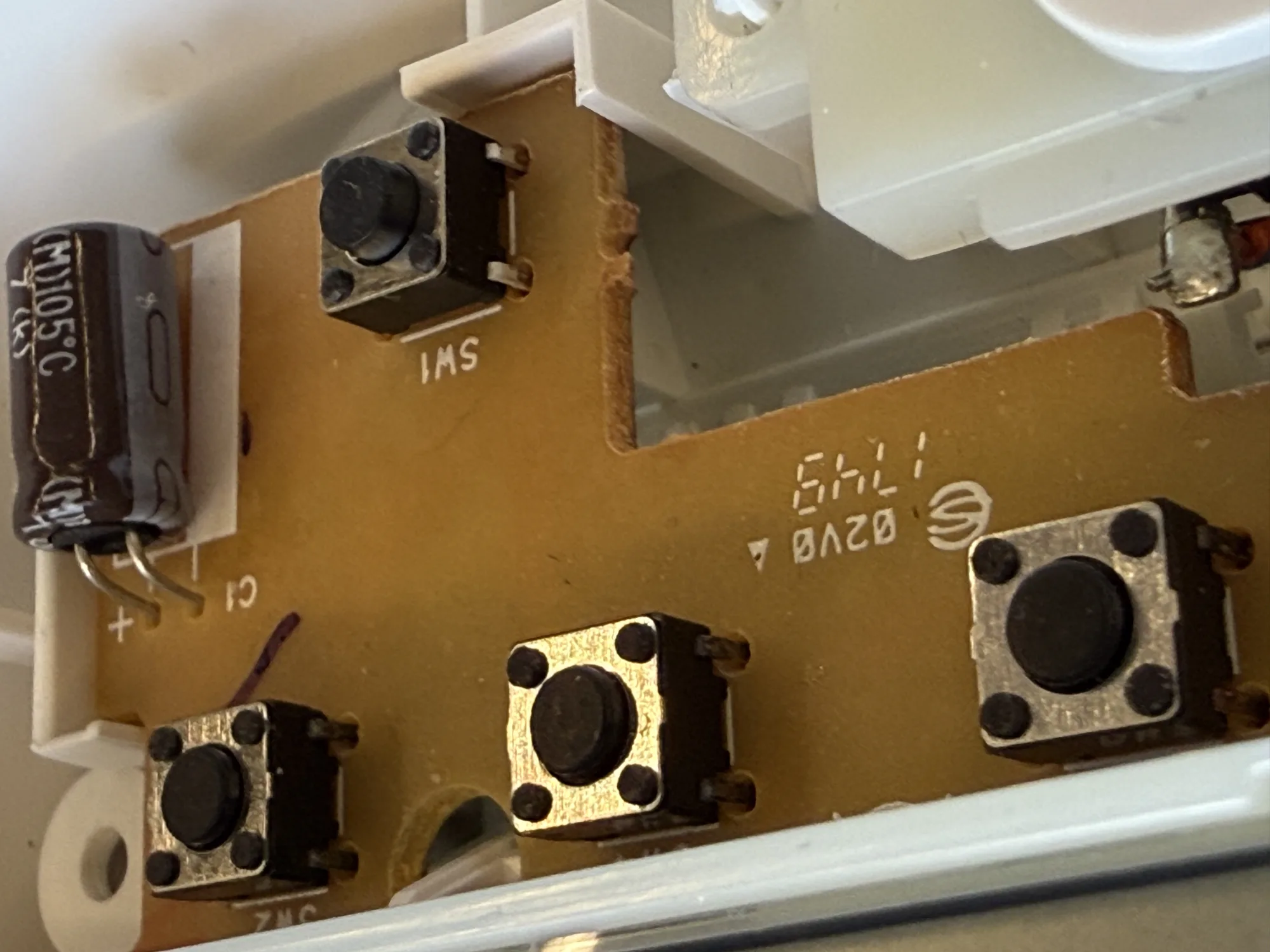
I trim the button lever that pushes the micro switch, making room for the taller micro switch to pop back.</p>

<h3 id="resolution">Resolution</h3>

<p>After assembly, the blood pressure measurement device “works”!</p>

<p>The customer measures their blood pressure and it indicates “high”.</p>]]></content><author><name>Berik</name></author><category term="Repairs" /><summary type="html"><![CDATA[Repair Café De Bieb, Utrecht]]></summary></entry><entry><title type="html">Stuck in Spin: Reviving a Jammed DVD Tray</title><link href="https://visschers.nu/repairs/2025/03/01/sony-dvd-player-tray.html" rel="alternate" type="text/html" title="Stuck in Spin: Reviving a Jammed DVD Tray" /><published>2025-03-01T11:00:00+00:00</published><updated>2025-03-01T11:00:00+00:00</updated><id>https://visschers.nu/repairs/2025/03/01/sony-dvd-player-tray</id><content type="html" xml:base="https://visschers.nu/repairs/2025/03/01/sony-dvd-player-tray.html"><![CDATA[<h2 id="repair-café-de-bieb-utrecht">Repair Café De Bieb, Utrecht</h2>

<p>The first repair of today is a Sony DVD player. I can’t tell you the exact version, but from what I’ve seen, they are all built similarly.
<img src="/assets/img/repairs/81835_original_local_1200x1050_v3_converted-2.webp" alt="Sony DVP-SR510H" /></p>

<p>On the inside, these machines have a box-standard DVD mechanism with a custom tray with flip door.
There is a mains power supply for which almost half the space inside the device is reserved.</p>

<p>The fault of this device is that the tray won’t open. When pressing the eject button, I hear some motor spinning, and there is a little movement of the tray door.
When I hold the flip door open, the tray comes out when I press eject.</p>

<p>This is a common issue with Tape, CD and DVD players. The elastic bands that are used as drive belts age and lose their tension.
In this machine, the elastic band seemed to be alright. However, once a new elastic band is installed, the tray would function properly.</p>

<h3 id="replacing-the-elastic-band">Replacing the elastic band</h3>

<p>To find the belt, I manually and <strong>gently</strong> slide the tray open. I wiggle the mechanism of the spindle lift to unlock the tray. I take my time here.</p>

<p>Once the tray is halfway out, I can see the elastic band. I remove it with a small screwdriver.</p>

<p>Repair Café De Bieb has a cheap set of elastic bands with different sizes. For this tray I use one of the smallest bands, less than 4cm circumference.</p>

<p>To install the new band, I first wrangle it underneath the tray and behind the drive wheel. Once in place, I tension the band and hook it behind the driven wheel.</p>

<h3 id="testing">Testing</h3>

<p>Once the belt is in place, I test opening and closing the tray five times in a row.</p>

<p>Works like a charm.</p>

<h3 id="references">References</h3>

<p>You can learn more about the elastic band replacement on <a href="https://www.ifixit.com/Guide/Samsung+DVD-HD850+Player+Rubber+Band+Replacement/32853">this iFixit page</a>, the brand is different, but the procedure is mostly the same.</p>

<p>Belts for repair can purchase <a href="https://www.bol.com/nl/nl/p/set-van-7-vierkante-rubberen-aandrijf-riemen-snaren-voor-cd-en-dvd-spelers-cassette-recorders/9300000157340946/">in a set</a> or <a href="https://webspareparts.com/en-nl/collections/cd-players-belts?srsltid=AfmBOoqUJXE8OTANbCj4GaJQamllozXLfzvQV8Oqamh_eStLjYSR-lFs">exactly sized for the use case</a>.</p>

<h3 id="second-sony-dvd-player-repair">Second Sony DVD player repair</h3>

<p>An almost exact copy of this machine, with the exact same issue is being repaired at the same time by one of the other repairman.
They find that the small size belt is too small for that machine. Apparently different versions and production dates have 
different belt size. The smaller belt is so tight that the tray motor won’t spin.
I don’t know the details, but they found another belt that did work for them.</p>]]></content><author><name>Berik</name></author><category term="Repairs" /><summary type="html"><![CDATA[Repair Café De Bieb, Utrecht]]></summary></entry></feed>